

Angle of Incidence (AOI) and Polarization
AOI and Snell’s Law
Angle of incidence (AOI) refers to the tilt of an optical filter with respect to the incident light (Figures 1a-1c). The simplest case is 0° AOI, where the incident light is normal to the filter.
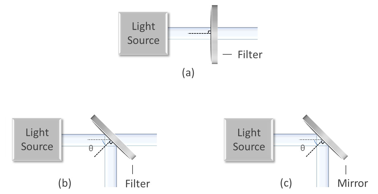
Figures 1a-1c: Diagrams showing (a) normal AOI for an optical filter, (b) 45° AOI for a dichroic filter, and (c) 45° AOI for a high-reflectivity mirror.
Whenever non-normal incident light hits an interface between two different media, such as air and glass, Snell’s law shows that the angle of incident light will change as the light passes into the second medium (Figure 2). The degree of change is dependent on the respective indices of refraction:
$$ { n_1 sin(\theta_1 )= n_2 sin(\theta_2 )} $$
Where:
- \(n_1\) and \(n_2\) = refractive index of each respective medium
- \(θ_1\) = angle of incidence within the incident medium
- \(θ_2\) = angle of refraction within the exit medium
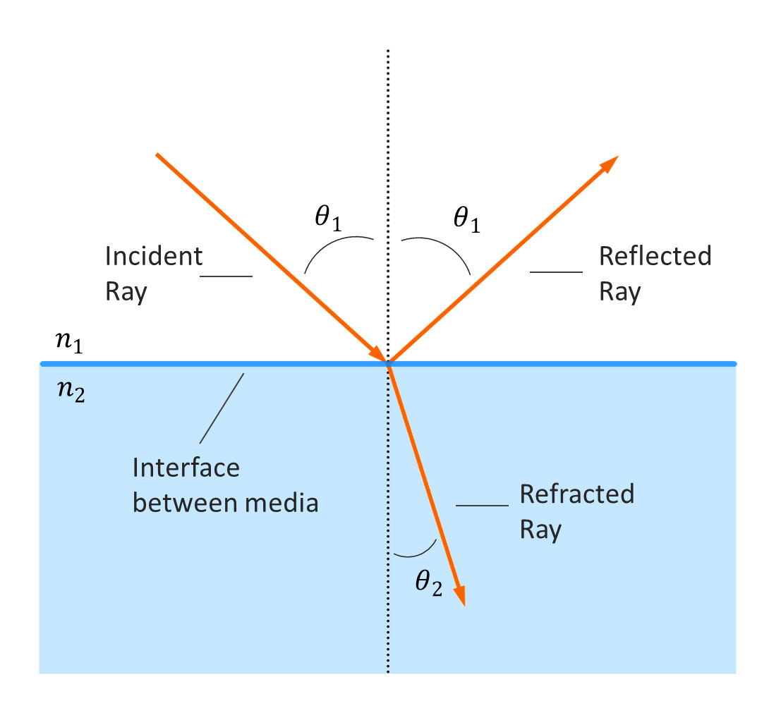
Figure 2: Diagram illustrating Snell’s law.
However, most optical filters are designed for use either in air or in vacuum systems where there is no difference between incident and exit media ( \(n_1 = n_2\) ). In this scenario, light passing through the filter will experience no net change between AOI and the angle of the transmitted beam, but a certain degree of beam deviation will occur at non-zero angles of incidence because of the refraction that occurs at each interface.
The amount of beam deviation depends on the refractive index and the thickness of the substrate. Larger beam deviation is seen with both thicker substrates and greater differences between the substrate refractive index and that of the entrance/exit medium. The thin-film coating may also contribute a negligible amount of beam deviation.
Less frequently, optical filters are designed with differing entrance and exit media, such as when one surface is adhered to a different optical component. In instances like this, both the system developer and the thin-film designer need to take into account the angle change and the beam deviation.
Angle Shift
As an optical interference filter is tilted away from normal, the transmission spectrum is “blue shifted,” which means the spectral features shift to shorter wavelengths (Figure 3). This angle shift becomes more pronounced with increasing AOI and can be calculated in collimated light and for relatively small angles of incidence using the following formula:
$$ { λ_θ= λ_o \sqrt{1 – \left(\frac{n_o}{n_{eff}}\sin θ\right)^2}} $$
Where:
- \(λ_θ\) = wavelength corresponding to the feature of interest at incident angle θ
- \(λ_o\) = wavelength corresponding to the feature of interest at normal incidence
- \(n_o\) = refractive index of incident medium
- \(n_{eff}\) = effective refractive index of the optical filter
- \(θ\) = angle of incidence
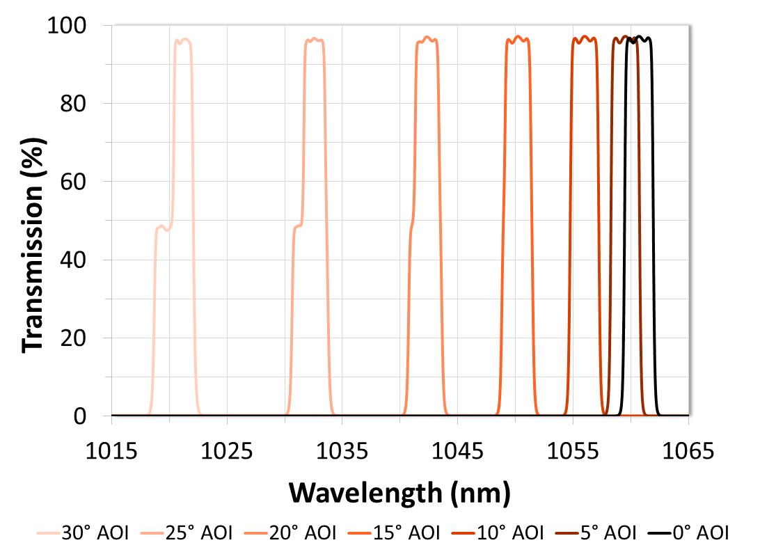
Figure 3: Example of angle shift. Bandpass filter theory data is shown at various angles of incidence for collimated light and average polarization. This narrowband filter was designed with a 1060.7 nm center wavelength at 0° AOI.
Effective refractive index can be used to predict angle shift, however, this variable is design-dependent, wavelength-dependent, and polarization-dependent. Therefore, different \(n_{eff}\) values for each optical filter design and polarization state will need to be determined to predict the shift of each spectral feature of interest.
Polarization-Dependent Shift
Because of a phenomenon known as Fresnel Reflection, optical filter spectra do not shift evenly for all polarization states (Figure 4). When non-normal incident light hits an interface between two different media with unequal indices of refraction, the amount of light transmitted or reflected varies depending on the polarization state.
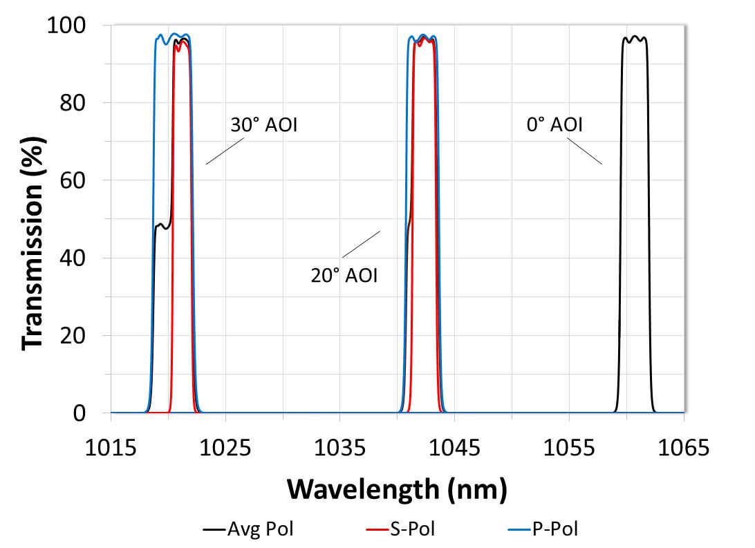
Figure 4: Graph demonstrating polarization-dependent shift using theory data for the same narrowband filter from figure 3.
The incident, reflected, and transmitted light rays at such an interface are commonly referred to in vector form, with each vector broken down into its main components relative to the plane of incidence that contains all three rays. The vector component parallel to the plane of incidence is known as p-polarized light, while the perpendicular component is called s-polarized (Figures 5 and 6).
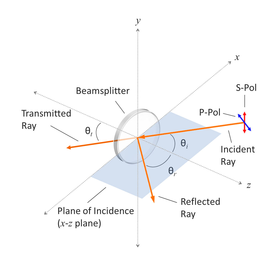
Figure 5: Diagram showing the plane of incidence relative to s-polarized and p-polarized light. In the Cartesian coordinate system, if the interface between incident media lies on the x-y plane, then the plane of incidence would be synonymous with the x-z plane.
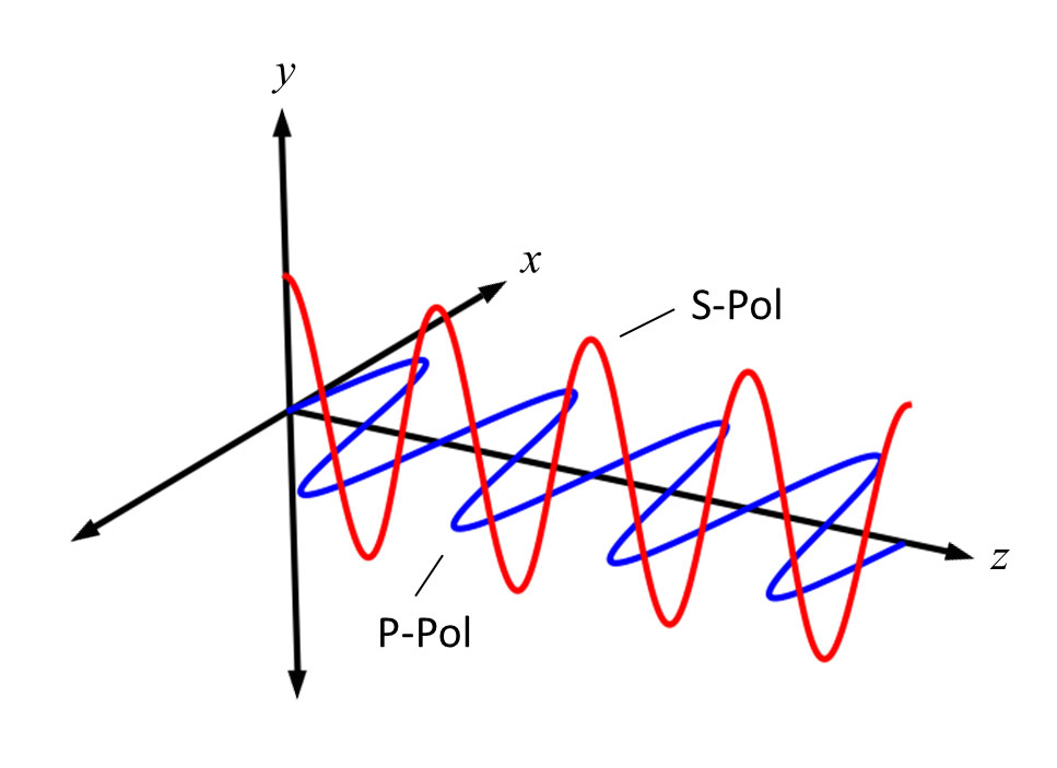
Figure 6: Diagram showing s-polarized and p-polarized light relative to the Cartesian coordinate system.
Because dielectric thin-film coatings are composed of many layers of alternating high and low index materials, incident light will be partially reflected or transmitted at each interface, resulting in internal interference. For any given wavelength, the thicknesses and refractive index of each layer are used to determine the total proportion of s and p-polarized incident light that will be reflected or transmitted.
As it turns out, s-polarized light at a given wavelength will always be reflected to a higher degree than p-polarized light. This phenomenon, known as polarization splitting, is readily apparent when evaluating the polarization-dependent shift of optical interference filter edges at non-zero angles of incidence.
For example, a cut-on, or longpass, edge will show p-polarized light shifting more than the corresponding s-polarized light for the same spectral feature because the optical filter is reflecting the s-polarized light to a higher degree. Conversely, and for the same reason, a cut-off, or shortpass, edge will show s-polarized light with a greater spectral shift. At larger angles of incidence, polarization splitting results in a hitch seen around the 50% point when measuring or evaluating using average polarization (Figures 3 and 4). This hitch is more pronounced on the cut-on edge. Polarization splitting also results in transmission loss and distorted passbands whenever a filter designed for use at 0˚ is used at large angles of incidence.
Since polarization splitting increases with increasing AOI, optical filters designed to be used at larger angles of incidence are more sensitive to slight AOI changes compared to filters designed to be used at 0˚ or other small AOI.
Evaluating AOI
There are several different methods to evaluate optical filter performance at non-zero angles of incidence:
Method #1: The simplest and most obvious method is to scan each filter at the specified nominal AOI and at the extremes of the AOI range. However, there are many cases where scanning all filters at angle is not ideal; examples are large volume orders, delicate parts where handling needs to be kept at a minimum, and odd-sized or odd-shaped parts that are difficult to scan at angle.
Method #2: The second method involves using AOI offsets determined from the filter theory traces for each AOI of interest. In this method, the wavelength difference between the normal and target AOI theory traces is determined for all specified spectral features. These values are then applied as offsets to the 0˚ AOI scans and used to evaluate the specifications at each angle. This method is useful when evaluating small AOI ranges and simple specifications.
Method #3: The third method, evaluating AOI using an optimization algorithm, is ideal for complex specifications and larger angles of incidence. In this method, 0˚ AOI measurement data are optimized using the corresponding theory trace. The optimized output can then be accurately modeled at any AOI and evaluated against the specifications.
Why Alluxa?
Alluxa’s team of experts has delivered key innovations to the field of optical thin-films. In addition to designing and constructing all of our own custom optical thin-film coating equipment, we invented a novel plasma deposition coating process that both increases the performance of our optical filters and decreases the time it takes to produce them.
By combining these innovations with state-of-the-art automation, proprietary control algorithms, and precision monitoring during the coating process, we are able to deliver low-cost, high-performance, custom thin-film optical filters for any application.
