

Thin-Film Optical Components for Use in Non-Linear Optical Systems
Dispersion controlled thin films boost the performance of NLO systems that utilize a femtosecond laser.
Some of the greatest recent advances seen in bio-imaging and detection are due to techniques that utilize non-linear optical (NLO) phenomena. These techniques have led to a Nobel prize, super-resolution images, label-free visualization of naturally occurring biomolecules, and greater freedom for working with in-vivo samples. Many NLO systems rely on the high peak pulse intensity of femtosecond lasers for signal generation. For this reason, the optical filters and mirrors integrated into these systems must have an appropriate laser damage rating, and the reflective components must be controlled for both group delay dispersion (GDD) and flatness. Choosing optical components that are specifically designed for NLO systems will ensure optimal signal strength, resolution, and image quality.
1. Overview
1.1 Dispersion in NLO systems
From super-resolution fluorescence microscopes to multi-model biomedical instruments, NLO systems have become incredibly sophisticated in recent years. These advancements have allowed for resolutions in the tens of nanometers, the visualization of both fluorescently tagged and unlabeled molecules in a single image, and the ability to perform in-vivo cancer research. In many NLO systems, ultra-short pulse femtosecond lasers with an extremely high peak pulse intensity are required to produce NLO signals. In these instruments, the pulsed beam is transmitted through or reflected off of several different optical components before ultimately reaching the sample. If these optical filters and mirrors are not specifically designed for use with femtosecond lasers, then the peak pulse intensity will decrease due to group delay dispersion (GDD) (Figure 1) every time the pulse train is reflected or transmitted. Because a reduction in peak pulse intensity will reduce the number of NLO signals, this compounded effect will ultimately result in poor instrument performance.
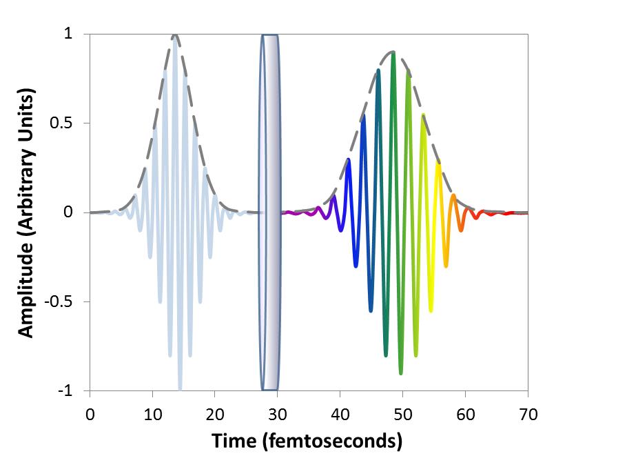
Figure 1. Example showing how decreased peak pulse intensity due to GDD can result when a femtosecond laser pulse is transmitted through an optical filter.
1.2 Thin Films for NLO Systems
The gold standard for both linear fluorescence and NLO applications are hard-coated, thin-film optical filters and high-reflectivity (HR) dielectric mirrors. In order to achieve optimal instrument performance, these thin-film components must meet a variety of challenging specifications. Excitation and emission filters should have extremely high transmission levels, greater than OD6 out-of-band blocking, and ultra-steep edges, and dichroic filters should have high levels of both transmission and reflection. Depending on the instrument, transmitted wavefront error (TWE) and many other factors should also be controlled.
Because NLO systems utilize short-pulse, high-intensity lasers, many of the optical components in these systems must be designed to meet even more challenging specifications. These include flatness, which reduces image distortion caused by the reflected wavefront error (RWE) generated from reflective components, and a laser damage rating that ensures durability under harsh conditions. However, in NLO systems that use a femtosecond laser for excitation, the thin-film mirrors that direct the excitation beam to the sample must also control GDD. These dispersion-controlled thin films allow for simultaneous control of both the phase and amplitude of laser light, resulting in minimal dispersion and minimal loss of peak pulse intensity. This translates into bright, high-contrast images and ultra-sensitive detection of target molecules.
2. Non-Linear Optical Systems
2.1 NLO Phenomena
Linear fluorescence occurs when photons of light at a particular wavelength excite the electrons within a fluorophore. As these electrons return to the ground state, they emit photons that are a longer wavelength than those that were initially absorbed. Therefore, in linear fluorescence systems, the excitation light is always higher in energy than the emission light.
Conversely, in NLO techniques such as multiphoton (MP) fluorescence microscopy, the simultaneous absorption of multiple longwave photons can actually result in emissions that are shorter in wavelength than the excitation light (Figure 2)[8].
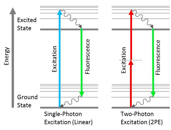
Figure 2. Jablonski diagrams showing linear vs. non-linear fluorescence. In linear single-photon excitation, the absorption of short wavelength photons results in a longer wavelength fluorescence emission. In non-linear two-photon excitation (2PE), the absorption of two long wavelength photons results in a shorter wavelength fluorescence emission.
2.2 NLO Microscopy
In addition to MP fluorescence microscopy, there are several other NLO methods that produce a variety of results (Figure 3). For example, the techniques of second and third harmonic generation fluorescence microscopy (SHG and THG, respectively) elicit a NLO response in molecules that lack a center of symmetry[1]. When multiple longwave photons are simultaneously absorbed by these molecules, photons that are ½ or ⅓ of the original wavelength are emitted. In coherent anti-stokes Raman scattering (CARS) and stimulated Raman scattering (SRS) techniques, laser pulses are used to produce Raman signals that are generated from the vibrational motion of molecules within the sample[2,3].
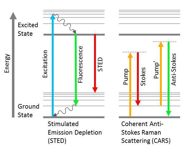
Figure 3. Jablonski diagrams showing multiple different NLO responses. Dashed lines indicate virtual states.
However, photon absorption does not always result in excitation of the sample. In stimulated emission depletion fluorescence microscopy (STED), for instance, longwave photons can be used to bring the electrons of an already excited sample back to the ground state without producing a spontaneous fluorescence response. In this technique, the STED beam is combined with an excitation laser that produces either a single or MP fluorescence response. A vortex phase plate (VPP) is used to produce a doughnut shaped pattern of the STED beam, resulting in a highly focused region of spontaneous fluorescence surrounded by a region of stimulated emission[7]. Once the beams in this configuration are mechanically scanned across the sample, the result is a super-resolution composite image that allows for the visualization of structures that can be as small as a single molecule[4].
Additionally, recent advancements in multi-modal NLO instruments have given researchers the ability to detect multiple NLO responses within a single sample. These imaging techniques allow researchers to gather a large amount of information about both the fluorescently labeled and unlabeled molecules within a tissue sample[9].
2.3 Short-Pulse Lasers
Another commonality seen between NLO systems is the utilization of short-pulse lasers to elicit the NLO response. Many of these systems utilize lasers with a pulse duration on the order of femtoseconds[6], with the most common being a mode-locked Ti:Sapphire laser. This laser is commonly used in MP, SHG, THG, and 2PE-STED microscopes[9] and can have a relatively broad emission spectrum that peaks around 800 nm. In CARS systems, optimal signal-to-noise ratios are achieved by using a picosecond laser[1], however, a femtosecond laser is sometimes used in multi-modal techniques that combine CARS with MP, SHG, or THG.
The pulse trains produced by femtosecond lasers have a high peak intensity which is necessary to ensure the simultaneous, or sequential, absorption of multiple photons by a single molecule[8]. Although the peak pulse intensity of femtosecond lasers is extremely high, the short pulse duration results in an overall energy intensity that is relatively low compared to a continuous wave (CW) laser. This reduces the probability of phototoxicity or photobleaching occurring within the sample. Preserving the peak pulse intensity of femtosecond lasers is imperative for the performance of NLO systems since a decrease in peak pulse intensity would decrease the probability of multiple photon absorption, which would result in signal reduction.
3. Thin-Film Mirrors and Optical Filters for NLO Systems
3.1 Controlling Group Delay Dispersion (GDD)
Thin-film filters and mirrors are made by depositing alternating layers of materials with varying indices of refraction onto a substrate. As light makes its way through the filter, part of the light reflects at each layer, resulting in internal interference. Depending on the thicknesses and configuration of the layers, the net result is that certain wavelengths of light are transmitted through the filter, while others are either absorbed by it or reflected off of it.
One of the simplest thin-film designs is a HR dielectric mirror known as a Bragg reflector. This thin-film coating consists of stacks of layer pairs, each composed of one high-index-material layer and one low-index-material layer, with each layer having ¼ wavelength of optical thickness. Although these dielectric mirrors are able to exceed 99.9% reflectivity across a broad range of wavelengths, they can result in a wavelength dependent phase shift of reflected light (Figure 4). This is particularly true when the mirror is designed to reflect over a large wavelength range by optimizing multiple quarter-wave stacks at different center wavelengths. This phase delay ultimately results in GDD and reduced peak pulse intensity when a femtosecond laser is reflected off of the mirror.
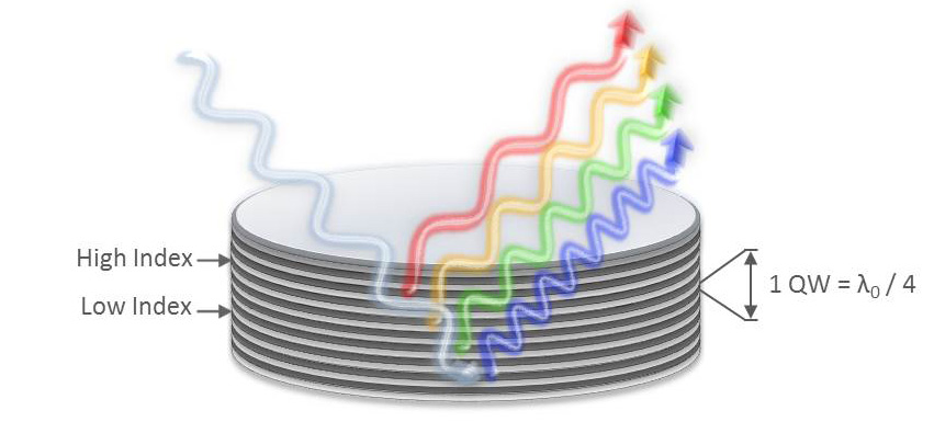
Figure 4. Example showing how a wavelength dependent phase shift of light reflected off of a dielectric mirror can occur when that mirror has not been optimized to control GDD.
There are currently many thin-film optical components on the market that attempt to counteract the effect of GDD. One option is a simple low-dispersion mirror that is designed to minimize GDD over a short region of high reflection by optimizing one quarter-wave stack at a single wavelength (Figure 5). This option is sufficient for minimizing dispersion for pulsed lasers that operate at a single wavelength. However, since Ti:Sapphire lasers can have a relatively broad emission range, a simple low dispersion mirror would not be sufficient for controlling GDD. Another possibility would be to use a combination of different chirped mirrors to direct the beam to the sample. Chirped mirrors are designed with layer thicknesses that vary throughout the layer stack. By changing the layer thicknesses, the designer is able to produce a variety of GDD effects that vary with wavelength in a controlled manner. When a pulsed laser is reflected off of one chirped mirror and then another that is designed to have the opposite GDD, net GDD can be controlled over a larger wavelength range than with a simple low-dispersion mirror.
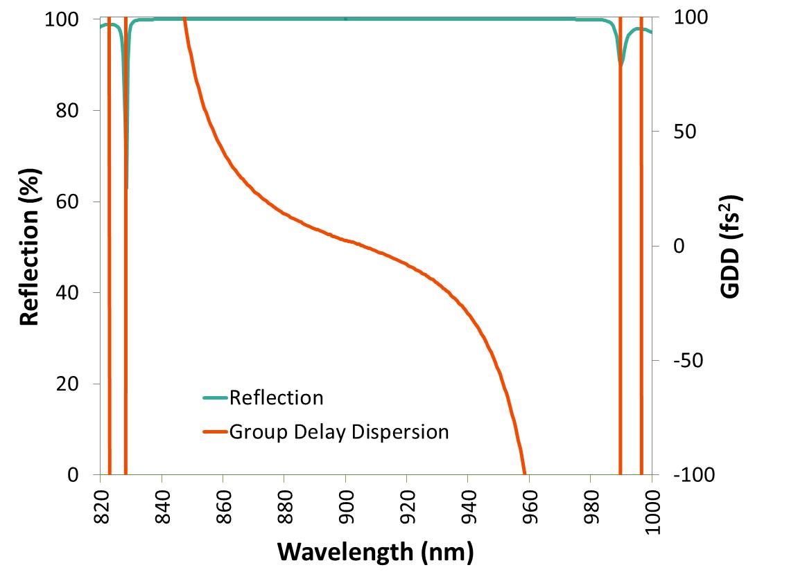
Figure 5. Reflection and GDD for a simple low-dispersion dielectric mirror designed by optimizing one quarter wave stack at a single wavelength.
However, continual improvements in thin-film design and coating capability have allowed for the ability to produce low dispersion thin-film mirrors that are able to achieve both greater than 99.5% reflection and low GDD across a broad range of wavelengths (Figure 6). These dispersion-controlled thin-film coatings allow the peak pulse intensity of femtosecond lasers to be preserved by a single optical component.
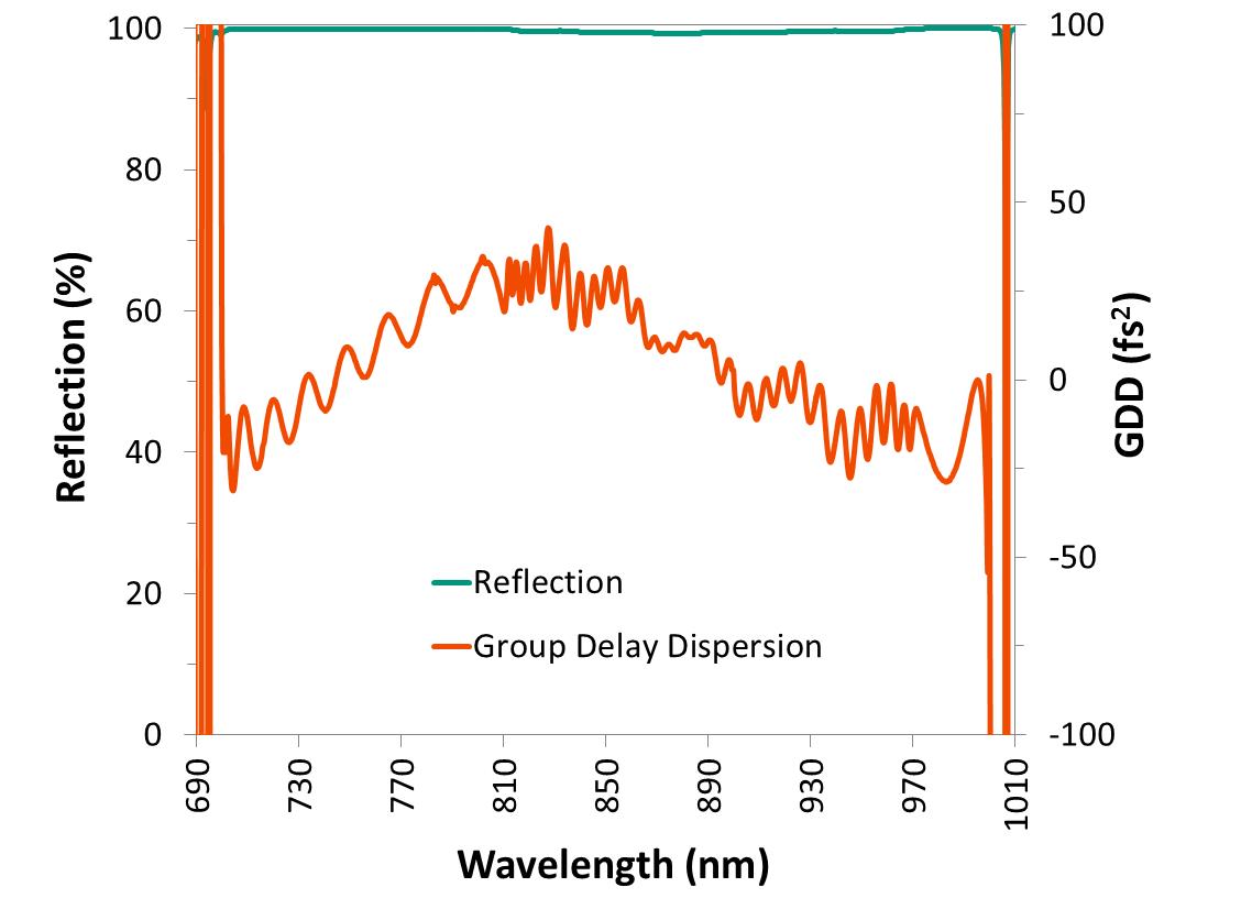
Figure 6. Reflection and GDD for a dispersion controlled thin-film mirror. Group delay dispersion is less than ± 45 fs2 across a broad range of wavelengths where reflection is close to 100%.
Although GDD is able to be controlled across a broad range of wavelengths corresponding to regions of reflection, the same cannot be said for regions of transmission. This is because transmission amplitude and phase responses are linked by a Hilbert transform. Therefore, any change the designer makes in the phase response immediately shows up in the amplitude response, and vice versa. This limitation applies to all light transmitted through thin-film filters, but does not apply to light reflected by the filter, as long as the filter design is asymmetric[5]. For this reason, dispersion can be controlled without sacrificing reflectivity, but attempts to control dispersion over a large wavelength range in a transmissive filter typically result in a decrease in transmission.
This ultimately creates a trade off since NLO systems can be configured where a dichroic beamsplitter either transmits the pulsed laser to the sample, or reflects it to the sample. When transmitted to the sample, peak pulse intensity may decrease due to GDD, however, the high reflectivity of the dichroic will allow for weak emission signals to reach the detector. When reflected to the sample, peak pulse intensity is able to be maintained by controlling GDD, however, weaker signals may not reach the detector. This is because controlling the GDD in the reflection band of the dichroic beamsplitter typically results in a decreased amplitude of the transmission band.
3.2 Laser-Induced Damage Threshold (LIDT) Testing
The thin-film optical components integrated into NLO systems must also be able to withstand high-intensity laser radiation for many years. Although most hard-coated thin-films are highly resistant to laser damage, it is best to specify a laser damage rating with the thin-film manufacturer for any mirrors, dichroic beamsplitters, and laser excitation filters that will be used in NLO instruments. This laser damage rating can be determined by performing LIDT testing with the appropriate femtosecond or picosecond laser.
3.3 Surface Flatness and Coating Stress
Surface flatness is another property that should be considered when selecting optical components for NLO systems. When a thin-film coating is deposited onto a substrate, the stress of the coating causes the substrate to bend, resulting in a bowl or dome shaped curvature (Figure 7). This coating-stress-induced curvature causes increased RWE, which can result in image distortion. Therefore, controlling flatness is critical for the thin-film mirrors and dichroic mirrors in NLO and other laser imaging systems.
This curvature can be minimized by multiple techniques, with the simplest being the use of a thicker substrate that will be less susceptible to coating stress. When a thinner substrate is required, the next option has traditionally been to add a backside compensation coating to the filter. However, both of these options come with a trade off. In order to minimize autofluorescence from the substrate reaching the detector, dichroics for fluorescence applications are necessarily coated on fused silica, which becomes quite expensive as thickness increases. When a backside compensation method is used, both the coating time and the complexity of the design are substantially increased since the backside coating must be thick enough to balance the coating stress of the filter[10].
Another option is a low-stress manufacturing process that produces ultra-flat dichroics and mirrors without the need for backside compensation (Figure 8). The dichroic filters in figures 7 & 8 are identical in terms of spectral response, coating thickness, and both substrate thickness and material. However, the dichroic produced using the low-stress process is considerably flatter than the dichroic manufactured using a standard method.
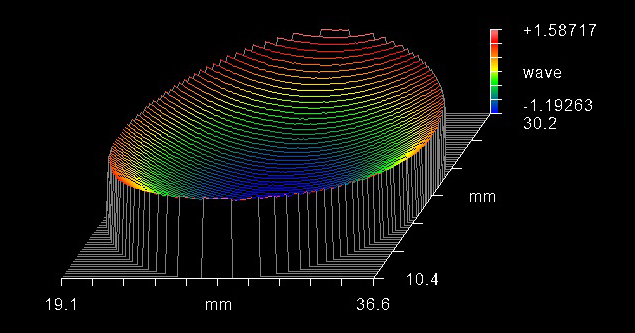
Figure 7. Interferometric surface flatness measurement showing the coating-stress induced curvature of a typical thin-film dichroic filter. Flatness was measured at 2.87 wave P-V over the clear aperture.
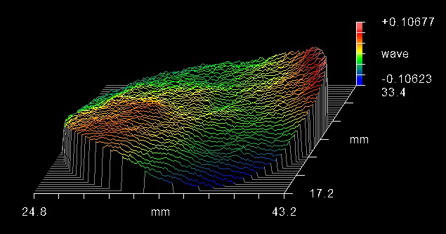
Figure 8. Interferometric measurement showing the low coating stress of an ultra-flat dichroic filter produced using a low-stress process. Flatness was measured at 0.21 wave P-V over the clear aperture.
Summary
NLO systems are responsible for some of the greatest recent advancements seen across biological disciplines. They have allowed researchers to accurately quantify super-resolution fluorescence images and to perform non-invasive, label-free imaging of in-vivo samples. However, the optical components integrated into NLO systems must be specifically designed for these instruments so that optimal performance can be achieved. This is especially important for NLO systems that utilize a femtosecond laser since these instruments require reflective components that minimize dispersion and preserve peak pulse intensity. Whatever your system requirements, the engineers at Alluxa will be able to help you customize high-performance thin films that are specifically designed for NLO systems.
Literature Cited
[1] Campagnola, P., Millard, A. C., Terasaki, M., Hoppe, P. E. Malone, C. J., and W. A. Mohler. (2002). Three-Dimensional High-Resolution Second-Harmonic Generation Imaging of Endogenous Structural Proteins in Biological Tissues. Biophysical Journal, 82(1): 493-508.
[2] Cheng, J., Volkmer, A., Book, L. D., and S. Xie. (2001). An Epi-Detected Coherent Anti-Stokes Raman Scattering (E-CARS) Microscope with High Spectral Resolution and High Sensitivity. Journal of Physical Chemistry B, 105(7): 1277-1280.
[3] Ji, M., Orringer, D. A., Freudiger, C. W., Ramkissoon, S., Liu, X., Lau, D., Golby, A. J., Norton, I., Hayashi, M., Agar, N. Y., Young, G. S., Spino, C., Santagata, S., Camelo-Piragua, S., Ligon, K. L., Sagher, O., and X. S. Xie. (2013). Rapid, label-free detection of brain tumors with stimulated Raman scattering microscopy. Science Translational Medicine, 5(201): 201ra119.
[4] Kasper, R., Harke, B., Forthmann, C., Tinnefeld, P., Hell, S. W., and M. Sauer. (2010). Single-molecule STED microscopy with photostable organic fluorophores. Small, 6(13): 1379-1384.
[5] Madsen, C. K. and J. H. Zhao. (1999). Optical Filter Design and Analysis. Hoboken, N. J. John Wiley & Sons, Inc. New York, NY.
[6] Tang, S., Krasieva, T. B., Zhongping, C., Tempea, G, and B. J. Tromberg. (2006). Effect of pulse duration on two-photon excited fluorescence and second harmonic generation in nonlinear optical microscopy. Journal of Biomedical Optics 11(2): 020501.
[7] Thorley, J. A., Pike, J., and J. Z. Rappoport. (2014). Super-resolution microscopy: A comparison of commercially available options. Fluorescence Microscopy: Super Resolution and Other Novel Techniques. Edited by Cornea, A. and P. M. Conn. Academic Press / Elsevier. London, UK. 185-197.
[8] Yamada, M., Lin, L. L., and T. W. Prow. (2014). Multiphoton microscopy applications in biology. Fluorescence Microscopy: Super Resolution and Other Novel Techniques. Edited by Cornea, A. and P. M. Conn. Academic Press / Elsevier. London, UK. 199-212.
[9] Yue, S., Slipchenko, M. N., and J. Cheng. (2011). Multimodal Nonlinear Optical Microscopy. Laser Photon Review, 5(4): 0.1002/lpor.201000027.
[10] Alluxa Engineering Staff. (2012). Thin Substrate, Dichroic and Polychroic Thin Film Filters Featuring Flatness Less Than 0.1 Waves RMS. Alluxa White Paper Series. https://alluxa.com/learning-center.
Why Alluxa?
Alluxa’s team of experts has delivered key innovations to the field of optical thin-films. In addition to designing and constructing all of our own custom optical thin-film coating equipment, we invented a novel plasma deposition coating process that both increases the performance of our optical filters and decreases the time it takes to produce them.
By combining these innovations with state-of-the-art automation, proprietary control algorithms, and precision monitoring during the coating process, we are able to deliver low-cost, high-performance, custom thin-film optical filters for any application.
Contact Alluxa for more information at info@alluxa.com
or visit our website at https://alluxa.com
All content copyright ©2020 Alluxa, Inc.
