

Specifying Plasma Deposited Hard Coated Optical Thin Film Filters
Due to their complex nature and diverse end-use applications, thin film optical filters have always been a challenge to specify. This paper defines the major types of filters and offers guidelines on how to specify key attributes, while also optimizing the cost.
Due to their complex nature and diverse end-use applications, thin film optical filters have always been a challenge to specify. This paper defines the major types of filters and offers guidelines on how to specify key attributes, while also optimizing the cost.
The filter types discussed include
- Band pass types of ultra-square high cavity count, ultra-narrow and soft coating replacements
- Dichroic and Polychroic tilted beamsplitter filters
Substrates
The most common substrates for thin film filters are Borofloat 33, NBK7, and fused silica (or equivalents). Alluxa strongly discourages using color glass and “green” float glass except for specialty or extremely low cost applications. For most applications, the thin film equivalent of a color glass is higher performance and lower cost. Color glass comes in limited sizes and shapes, which constrains the effective load sizes of each coating lot. Green glass suffers from scatter, absorption and auto-fluorescence and other “low quality” flaws. Laminated filters which sandwich multiple green glass substrates between fragile and environmentally sensitive coatings should be avoided other than for laboratory scale demonstrations.
Precision filters need to be deposited on flat substrates. Curved substrates can be used, but they introduce thickness variations which degrade performance.
Background: Light sources, detectors
Clearly a filter need not be specified in wavelength for transmission range, reflection range, or blocking range beyond either the light source range or the detector range. Silicon detectors and photomultipliers for example have very defined response curves, and nothing is gained other than added cost by specifying past its response curve. Similarly, for LED and laser diode “clean up” filter applications, there is typically no benefit to specifying the blocking range past the relatively narrow emission spectrum.
Transmission and blocking should be specified as average levels unless a discrete light source such as a laser is required to be transmitted or blocked. Thin films filters often display uneven blocking levels and very narrow spikes can easily rise 1 or even 2 OD above the average blocking levels, but because spikes have a very narrow spectral bandwidth they don’t have a meaningful impact on blocking level performance or signal to noise ratio.
Bandpass Filters
Bandpass filters select a spectral band to transmit while rejecting light outside that band. Historically, these were specified with half-power bandwidth (HPBW), peak transmission, and center wavelength. (CWL). A more precise and modern way to specify is to simply provide a range of wavelengths to transmit, the level of transmission and a range of wavelengths to reject. The gap between these ranges is used as a single specification to capture the tolerance of the filter for centering, filter slope, uniformity and manufacturing margin.
Bandpass filters are generally used at near zero Angle of Incidence (AOI). Angles larger than zero degrade performance due to the angle sensitivity of the filter. Filters shift with angle roughly proportional to the square of the angle and the inverse of the square of the effective index. The larger the angle of incidence, the greater the issue angle creates. Angles also create polarization splitting where the S & P polarization states have different performances as a function of angle within the filter design. Because each polarization state essentially creates a different filter function as angle increases, polarization splitting typically degrades the performance of the filter.
Bandpass filters come in two types, a resonant cavity Fabry-Perot structure or a long pass/short pass structure. ‘Squareness’ of a bandpass filter is a function of number of cavities for resonant cavity type filters and the number of layers for a LWP and SWP type filter. Figure 1 shows the effect of increasing the number of cavities. Figure 2 shows typical performance for a wide band high cavity count filter and Figure 3 shows a flat top narrow band cavity filter.
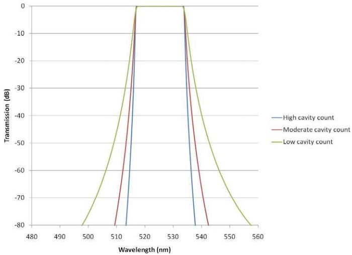
Figure 1. Squareness of narrow band pass filter is a function of number of cavities.
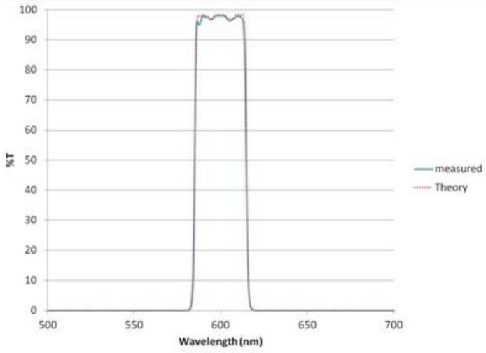
Figure 2. Typical high cavity count thin film cavity band pass filter.
Table 1.
Bandpass filter specification guidelines
| Term/Parameter | Description | High Performance | Standard | Lowest Cost |
| Center wavelength | Center of passband. This should be used only as a nominal value | +/- 0.25% of cwl | +/- 0.5% of cwl | +/- 1% of cwl |
| Transmission | Average transmission over desired band | >95% | >90% | >85% |
| Blocking ranges | Range of wavelengths required to suppress | 200 nm – 1200 nm | 300 nm – 1100 nm | Optimized for detector and light source |
| Passband to blocking band delta | Spectral gap between the passband and blocking band giving tolerance for slope, centering, etc. | <1% of wavelength | 1% to 3% of wavelength | >3% of wavelength |
| Blocking levels | Blocking suppression levels in log units average over the band | 6 OD average, with 10 OD in specified bands | 5 OD average | 4 OD average integrated over light and detector |
| AOI and cone angle | Range of angles about the primary AOI | Normal AOI with <10 degrees cone angle | Normal AOI with <10 degrees cone angle | Normal AOI |
Ultra-Narrow Bandpass Filters
Ultra-narrow bandpass filters generally refer to the class of bandpass filters with bandwidths less than 1% of wavelength. Key attributes are blocking levels, transmission and bandwidth. Most applications for narrow bandpass filters are designed to transmit a single wavelength such as a laser or an emission line.
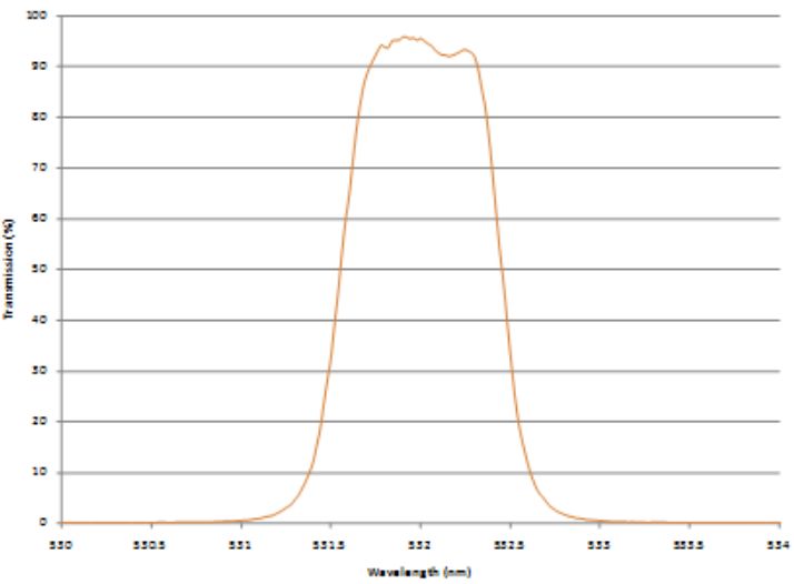
Figure 3. Ultra-narrow and flat top band pass filter with bandwidth <1nm at 532nm.
Table 2.
Ultra-narrow band pass filter specification guidelines.
| Term/Parameter | Description | High Performance | Standard | Lowest Cost |
| Center wavelength | Center of passband. This should be used only as a nominal value | +/- 0.1% of cwl (nominal) | +/- 0.25% of cwl | +/- 0.5% of cwl |
| Transmission | Transmission at the desired line | >95% | >90% | >80% |
| Bandwidth | FWHM | <0.2% of CWL | <0.5% of CWL | <1% |
| Blocking ranges | Range of wavelengths required to suppress | 200 nm – 1200 nm | 300 nm – 1100 nm | Optimized for detector and light source |
| Passband to blocking band delta | Spectral gap between the passband and blocking band giving tolerance for slope, centering, etc. | <0.5% of wavelength | <1% of wavelength | >2% of wavelength |
| Blocking levels | Blocking suppression levels in log units average over the band | 6 OD average | 5 OD average | 4 OD average integrated over light and detector |
| AOI and cone angle | Range of angles about the primary AOI | Normal AOI with <10 degrees cone angle | Normal AOI with <10 degrees cone angle | Normal AOI |
Multi-Bandpass Filter
A multi-bandpass filter is simply a band pass filter that transmits multiple pass bands or multiple spectral regions and has blocking regions in between the transmitted regions as shown in Figure 2. To specify these filters follow the same guidelines as for single bandpass filters above; however, the tolerances should be more carefully considered to minimize cost. A multi-bandpass filter is generally more challenging to deposit than creating two single bandpass filters separately.
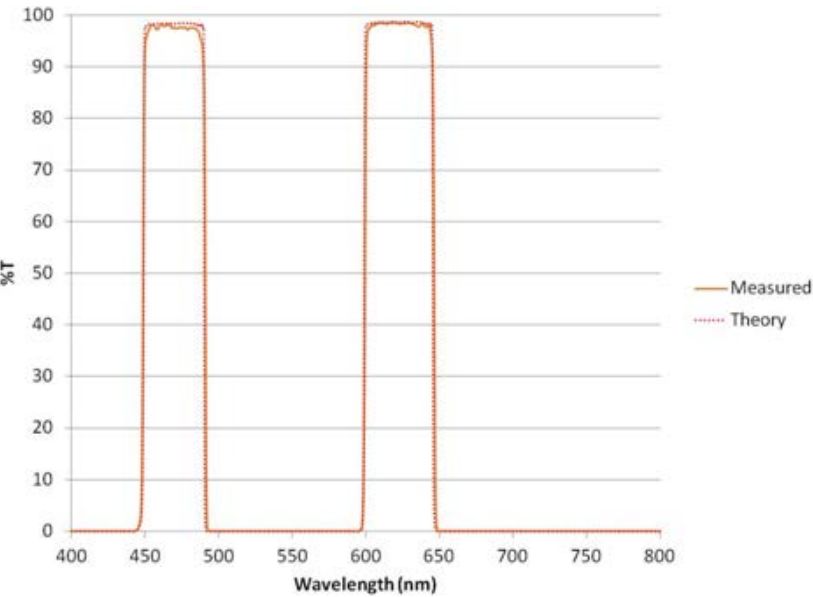
Figure 4. Multi-bandpass filter theory and measured.
Table 3.
Multi-band pass filter specification guidelines
| Term/Parameter | Description | High Performance | Standard | Lowest Cost |
| Center wavelength | Center of passband. This should be used only as a nominal value | +/- 0.4% of cwl | +/- 0.75% of cwl | +/- 1% of cwl |
| Transmission | Average transmission over desired band | >95% | >90% | >85% |
| Blocking ranges | Range of wavelengths required to suppress | 200 nm – 1200 nm | 300 nm – 1100 nm | Optimized for detector and light source |
| Passband to blocking band delta | Spectral gap between the passband and blocking band giving tolerance for slope, centering, etc. | <1% of wavelength | 1% to 3% of wavelength | >3% of wavelength |
| Blocking levels | Blocking suppression levels in log units average over the band | 6 OD average, with 10 OD in specified bands | 5 OD average | 4 OD average integrated over light and detector |
| AOI and cone angle | Range of angles about the primary AOI | Normal AOI with <10 degrees cone angle | Normal AOI with <10 degrees cone angle | Normal AOI |
Soft Coating Replacement Filters
“Soft coatings”, also known as “laminated coatings” are well known to possess poor environmental durability, poor temperature stability, low transmission, high optical scatter and low blocking levels, yet they are still widely used due to their low cost, ready availability and legacy status. Alluxa’s proprietary high speed plasma deposition technology for the first time delivers the optical performance and durability of hard coated thin film optical filters at laminated soft coating pricing.
Typical performance of soft coating replacement filters for a variety of different wavelengths from the blue to the NIR is shown in Figure 5. These are generally deposited on borofloat for cost purposes.
Price is generally the most important parameter for these filters and Table 1 price sensitive column is most appropriate.
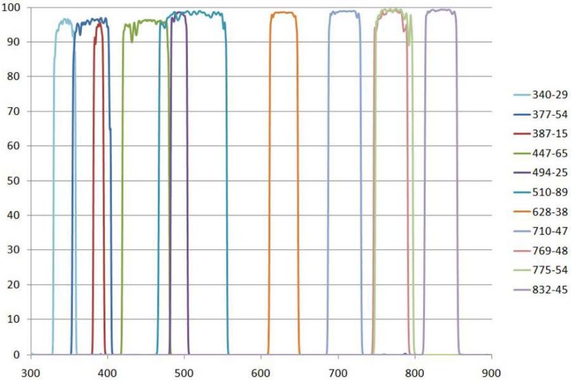
Figure 5. A variety of soft coating replacement filters. The bandwidth is typically between 10 and 50nm with blocking > OD4. Substrates are borofloat to reduce cost.
Tilted Filters – Dichroic and Trichroic Filter
Dichroic filters refer to the family of filter that are tilted and reflect and transmit. Specifying Dichroics and Polychroics filters is much like multi-bandpass filters, and primarily involves selecting the desired pass bands and blocking bands and substrate type and thickness. The spectral gaps between the bands are the primary driver of coating complexity and cost. Due to complexity of suppressing polarization splitting as well as other effects, the performance of tilted filters is lower than the filters used at normal incidence.
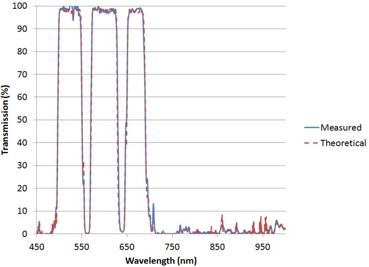
Figure 6. Multiband dichroic beamsplitter used at 45 degrees vs. theory.
45 degrees is a standard angle for mounting, however, the lower the angle the easier it is to achieve performance of slope, blocking and transmission. Similarly, the lower the angular range of the beam, and more collimated, the better the performance in general. Table 4 below shows a summary of recommended specifications for polychroic and dichroic filters.
Table 4.
Summary of specifications for Dichroics and Polychroics
| Term/Parameter | Description | High Performance | Standard | Lowest Cost |
| Center wavelength | Center of pass band. This should be used only as a nominal value | +/- 1% (nominal) | +/- 2% (nominal) | +/- 3% (nominal) |
| Pass band Transmission | Transmission average across pass band | >95% | >90% | >85% |
| Pass band width | Range of wavelengths required to transmit | >1% wide 310 – 1100nm | >2% wide 310 nm – 1100nm | >4% wide 310 – 1100nm |
| Blocking band | Range of wavelengths required to suppress | >1% wide 310 – 1100nm | 300 nm – 1100 nm | Optimized for detector and light source |
| Passband to blocking band delta | Spectral gap between the passband and blocking band giving tolerance for slope, centering, etc. | <1% of wavelength | >2% wide 310 nm – 1100nm | Optimized for detector and light source |
| Blocking levels | Blocking suppression levels in log units average over the band | 1% average across blocking band | 5% average across blocking band | 10% average across blocking band |
| Pass band to blocking band gaps | Spectral gap between the pass band and blocking band giving tolerance for slope, centering, etc. | <1% of wavelength | 1% to 3% of wavelength | >3% of wavelength |
| Substrate | Thickness and type | 1mm or less on fused silica | 2mm on fused silica or polished borofloat | Borofloat |
| Flatness | RMS flatness measured at 632nm using interferometer | <0.1wave RMS/inch | 0.5 wave RMS/inch | 1 wave RMS/inch |
Summary
Modern hard coated optical thin film filters are nearly infinitely flexible in capability. Single band, multiband, dichroic tilted filters are all available with high transmission and excellent blocking. However, due to their complex nature and diverse end-use applications, thin film optical filters have always been a challenge to specify. Guidelines presented in this paper on how to specify key attributes, while also optimizing the cost, are meant to help the designer with selecting specifications.
Alluxa
Alluxa designs and manufactures next generation hard coated optical filters using a proprietary plasma deposition process in Santa Rosa, CA. Alluxa’s unique, purpose-built deposition platform and control systems were designed, developed, and built by our team in Santa Rosa, CA to address the demanding requirements of the next generation of systems and instruments. This unique technology allows Alluxa to create the world’s most challenging filters at breakthrough price points.
Contact Alluxa for more information at info@alluxa.com
or visit our website at https://alluxa.com
All content copyright ©2013 Alluxa
