

Advanced Plasma Deposition Improves Ultra Narrowband Optical Filters
A novel computer-controlled deposition system for multicavity filters improves their spectral precision and contrast.
Narrowband filters are a critical technology for a variety of applications such as lidar (light detection and ranging), laser cleanup, chemical and gas sensing, instrumentation, and astronomy. The design principles are well known and relatively simple. All designs rely on stacked Fabry-Pérot resonant cavities with dielectric reflectors composed of layers a quarter of a wavelength thick, spaced apart by cavities multiple half-wavelengths across. Several cavity filters are used in combination to ‘square up’ the spectral wave shape, resulting in the transmitted light having a ‘flat-topped’ spectrum when compared with that from light passed through single-cavity filters, which has a sharp, peaked spectral shape. Such multicavity filters also have much steeper rejection responses than single-cavity filters: the less-steep spectral slopes of single-cavity filters can compromise signal-to-noise in narrowband detection.
Creating multicavity filters is a challenge for deposition process control systems. It invariably introduces undesirable ripple (wavelength-dependent variation in attenuation of the signal as it enters the filter), resulting in signal loss in the pass band, the spectral range over which the filter has high transmittance. We use a computer-controlled variation on the turning point method1 of thickness control for each individual layer, where the filter is constantly measured and variations in thickness compensated for, taking into account thickness errors associated with multiple layers. The system allows us to make remarkably reproducible filters with very low ripple, producing a signal shape with steep slopes that consistently match theory.
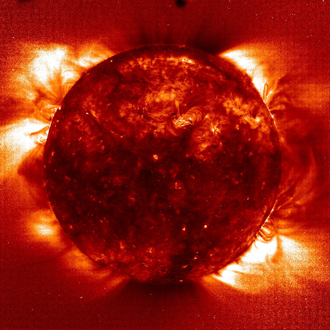
Figure 1. Solar image using a narrowband H-alpha filter combined with a narrowband etalon.
Ultra-narrowband filters are capable of producing images with astounding contrast (see Figure 1). This image of the Sun has had its light passed through an H-alpha filter, which is designed to only pass the emission of the H-alpha line at 656.28nm while blocking the remaining light. This dramatically improves the contrast of the image. The higher the transmission and narrower the filter, the better the contrast enhancement. A filter of approximately 1nm bandwidth at this wavelength provides roughly a thousandfold increase in contrast to a silicon-based detector camera system. It is important to note that at these narrow bandwidths, commercial instruments become incapable of measuring the filters effectively and specialized metrology techniques are required, as described elsewhere in application notes.2,3
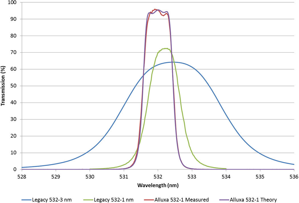
Figure 2. Measured results of fully blocked three-cavity flat-top band pass filter with 0.94nm bandwidth compared with the other known deposition methods for ultra-narrowband pass filters.
Figure 2 shows the measured and theoretical response of a 532nm three-cavity flat-top band pass filter fully blocked from 350 to 900nm at OD4 levels (an optical density of 4). Shown alongside are typical state-of-the-art narrowband pass filters from legacy deposition processes such as ion-assisted electron beam. Filters from 330 to >2000nm can be built to similar or even narrower specifications.
Ultra-narrowband filters require extremely low extinction coefficients of the deposited materials due to the resonance in the pass band, which results in loss of intensity. A filter with a bandwidth of 1nm requires extinction coefficients of less than 10ppm to limit losses to acceptable levels. The plasma PVD (physical vapor deposition) hard-coated filters we make routinely have transmission over 95% with a fully blocked configuration requiring OD4, OD5, or greater level of blocking over 200–1200nm and longer.
All thin-film filters exhibit a shift in the wavelength of the pass band dependent on the angle of incidence. The net effect of greater cone angle is to round the slopes of the spectrum and reduce the wavelength. We minimize the angle shift by using design techniques that take into account refractive index. An example is the filter shown in Figure 2, which can operate with F-numbers as low as F5. Figure 3 shows the calculated response of various F-numbers on the filter response. As indicated by the plot, filters to be used in low F-number systems should be biased slightly higher for the central peak to reach 100% transmittance.
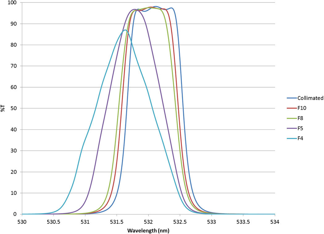
Figure 3. Filter function as calculated for various F-numbers. T: Transmission.
The bulk of narrowband applications use filters in the range of diameters from 12.5 to 50mm. By carefully controlling uniformity of physical and optical thickness, we have produced filters up to 250mm in diameter. Figure 4 shows the measured result of various radii of a 250mm flat-top band pass filter on a 250mm wafer designed to transmit the 532nm laser line.
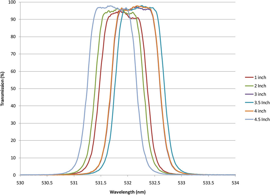
Figure 4. Measured results of 250mm-diameter, fully blocked three-cavity flat-top band pass filter with 0.94nm bandwidth.
Unlike narrowband filters made with other deposition technologies, our ultra-narrowband filters can be coupled with wide and deep blocking performance at state-of-the-art levels (up to and beyond OD6) without sacrificing transmission performance. Typical performance specifications are a 400 to 900nm range around the pass band with OD4, OD5, or OD6 blocking performance. Our filters are regularly subjected to both telecom and MIL standards (as used by the US Department of Defense). The MIL standard for operation in humid environments has a requirement of 10×24h temperature/humidity cycles with extremes of 60°C/95% relative humidity, 30°C/95% relative humidity, and 20°C/95% relative humidity, while the Telcordia GR-1221 Damp Heat UNC requirement is 2000h at 85°C/85% relative humidity. The filters we produce show no measurable change to spectral performance or physical appearance after these tests. In addition to environmental testing, our filters also meet Department of Defense durability requirements (MIL 48497A).
Our hard-coated ultra-narrowband pass filters have a very low wavelength dependence on temperature. It varies depending on the substrate choice and the type of coating design. But for a typical 532nm ultra-narrowband filter on a Schott BK7 glass substrate, the center wavelength will shift approximately 2.5pm/°C. Lower values of temperature shift can be created on request by optimizing the design parameters.
In summary, our computer-controlled method of thin-film deposition allows us to create multicavity filters with greater wavelength precision and greater contrast. Our future work will focus on further decreasing the bandwidths of our high-transmission, hard-coated flat-top filters to values of less than 0.5nm, and further improving the filter function squareness. We also plan to explore the reduction of the transmitted wavefront error, a major culprit in image distortion.
Article published in SPIE Optical Design & Engineering December 18th, 2013.
Michael Scobey, Peter Egerton, Rance Fortenberry
Alluxa
Santa Rosa, CA
References:
1. H. A. Macleod, D. Richmond, The effects of errors on the optical monitoring of narrow-band all-dielectric thin film optical filters, Opt. Acta 21, p. 429-443, 1974.
2. Alluxa Engineering Staff, New metrology techniques for advanced thin film optical filters, Alluxa White Paper Series, 2012. https://alluxa.com/learning-center
3. T. Burt, Characterizing sub-nanometer narrow bandpass filters using a Cary 400/500, Tech. Rep. SI-A-1193 Agilent Technologies Inc., 2011.
