

Flat Top, Ultra-Narrow Bandpass Optical Filters Using Plasma Deposited Hard Oxide Coatings
Thin film optical filters with ultra-narrow bandwidth, high transmission and flat spectral profiles improve optical system performance for a variety of applications such as LIDAR, laser cleanup, and instrumentation.
Alluxa’s new class of ultra-narrow filters are designed for applications such as laser clean up, LIDAR, telecommunications and instrumentation and offer the narrowest and “squarest” filter profiles in the visible and NIR as well as transmission levels that approach 100%. They are manufactured with Alluxa’s proprietary advanced plasma enhanced PVD process using durable, hard metal-oxide, front surface thin films and are virtually impervious to environmental effects.
Basic Bandpass Theory
The design principles of resonant cavity thin film optical bandpass filters are well known and rely on stacked Fabry-Perot resonant cavities. Fabry-Perot resonant thin film optical cavities are a pair of dielectric reflectors separated by a spacer layer of a halfwave thickness or a multiple halfwave of optical thickness. A cavity can be between 3 and 50 layers depending on bandwidth. An excellent book describing the subject further is “Thin Film Optical Filters” by Dr. Angus Macleod. Designing filters to have improved squareness , or steeper slopes, is a relatively simple matter of adding more cavities to the filter design as shown in Figure 1 below. To make a filter narrower or wider, the designer increases or decreases the thickness of the spacer layer or increases or decreases the reflectivity of the dielectric mirrors.
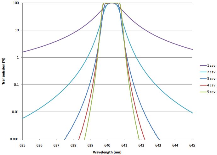
Figure 1.Filter squareness is a direct function of number of cavities count.
Adding cavities challenges the deposition process control system, and invariably introduces undesirable ripple and loss to the passband. Alluxa has created a new low noise monitoring system that provides the utmost in layer thickness accuracy, which enables cavities to be added almost without limit. The novel, advanced computer control system constantly measures the filter function and compensates for thickness errors associated with prior layers. The system produces filters with remarkably low ripple and steep slopes that consistently match theory.
The “Ultra” Class of Flat Top Narrow Band Filters
Flat top, ultra-narrow hard coated bandpass filters were pioneered by the telecommunications industry in the 1990s and achieved amazingly narrow and high performance results. The narrowest published result was “25 GHz thin film optical filter” presented at OFC in 2002 by Scobey and Fortenberry and demonstrated a bandwidth of .1nm at 1550nm. Filters this narrow suffered however from severe phase delay effects (chromatic dispersion) across the passband due to the high resonant lifetime and were not useful for real world telecommunication systems. These filters were also very small, on the order of a few mm in size, and so limited in usefulness to instrumentation designers.
Narrow band filters in the visible region with useful diameters of 25mm to 50mm or larger have been traditionally limited to between 2 and 5 nm in bandwidth due to control system limitations, optical loss and uniformity problems. Alluxa has developed a new class of ultra-narrow bandpass filters that solve these manufacturing issues and can produce bandwidths of less than 1nm in the visible and near IR with flat top and square filters shapes. The measured result of a fully blocked 532 bandpass filter is shown in Figure 2 below. Note that measuring filters this narrow require special spectrophotometer setups. See Alluxa’s related paper New Metrology Techniques for Advanced Thin Film Optical Filters for discussion of this topic.
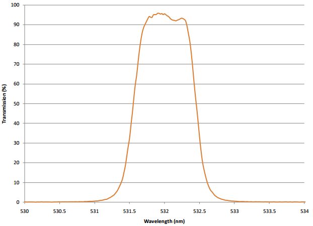
Figure 2.Measured Transmission of a fully blocked 3 cavity flat top bandpass filter at 532nm with 0.92nm bandwidth and T>92%.
Large Formats
The bulk of narrowband applications use filters in the 12.5mm to 50mm in diameter. By carefully controlling uniformity of physical and optical thickness, Alluxa has for the first time produced flat top ultra-narrowband filters economically priced in formats up to 250mm. Figure 3 shows the measured result of various radii of a 250mm flat top bandpass on a 250mm wafer designed to transmit the 532nm laser line.
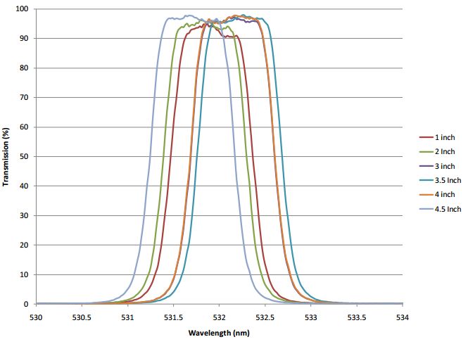
Figure 3.Measured results of 250mm diameter, fully blocked 3 cavity flat top bandpass filter with 0.94nm bandwidth with T>90%.
Shift with Angle
The filter function of a thin film filter constructed of resonant cavities shifts as it is tilted away from normal to shorter wavelengths. The shape itself stays much the same until relatively high angles where polarization effects begin to become a factor. It is well known that this relative shift in wavelength changes proportionally to the square of the angle of tilt, for tilts up to a few tens of degrees. The proportionality constant is the inverse of the square of the effective index times two, where the effective index is a property of the cavities design as well as the coating materials used. This effect is illustrated in the angle measurements of the narrowband filter shown in Figure 4.
The user needs to take the angle shift effect into consideration when determining the Field of View (FOV) requirements of the filter. For larger FOV applications, the filter bandwidth may need to be increased.
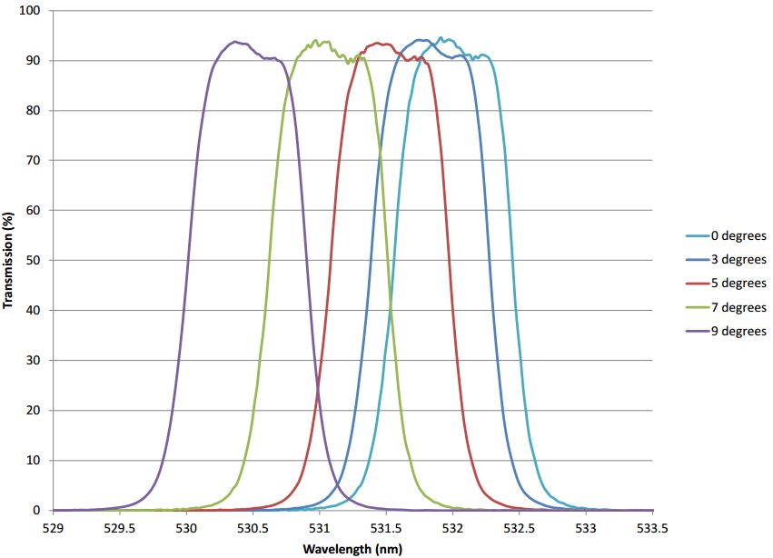
Figure 4.Shift in wavelength with angle of incidence for a measured laser line filter at 532 nm.
Blocking Performance
Alluxa’s ultra-narrow filters can be coupled with additional filtering structures to create wide and deep blocking performance at state of the art levels (up to and beyond OD6) without sacrificing transmission performance. Typical performance specifications are a 400 nm to 1100 nm range around the passband with OD4, OD5, or OD6 blocking performance. Blocking levels typically do not have an impact on transmission, but it can add to the cost of manufacture of the filter.
Optimizing Performance and Cost
The wide variety of filter performance requirements that can be designed into Alluxa’s ultra-narrow bandpass filters offer the opportunity for optimal performance / cost balance in the finished filter. The most fertile areas for considering performance / cost tradeoff are: blocking range and level, substrate material, and spectral tolerances on filter attributes such as center wavelength (CWL) and full width – half maximum (FWHM), and size and clear aperture.
While the blocking requirements do not meaningfully affect the transmission levels achieved in Alluxa’s filters, it does add cost and complexity to the design and coating process due to the additional layers required. In many cases, the cost of the filter may be optimized by carefully addressing the exact blocking range required. In laser cleanup situations, only the ASE spectrum of the laser may need to be blocked to high levels. Alternatively, in a detection application, the blocking requirements will be different depending on whether or not the system is using a PMT, Silicon detector or otherwise. Factoring in the responsivity of the detector can further reduce the layer count in the filter and, therefore, the cost.
In terms of substrate material, Alluxa filters are usually coated on either UV grade fused silica or Borofloat 33 in varying sizes and thicknesses. In most applications, Borofloat 33 offers a sufficiently high quality, durable optical glass. In some cases, the use of fused silica is necessary – particularly in applications where there is extreme sensitivity to auto-fluorescence of the substrate material.
When considering the spectral profile of ultra-narrow filters, additional constraints on the filter shape such as CWL and FHWM tolerances can have significant impact on cost. The simplest method for specification of the spectral profile is to call for an absolute transmission at a defined wavelength and to call for the bandwidth to be less than a defined spacing. The filter in the figure above was specified in this way: > 92% Transmission at 532 nm and < 1 nm FWHM. Any additional tolerances to define the spectral shape should be considered in terms of their value to the application as the effect on cost can be large.
Summary
Flat top and square narrowband filters of less than 1nm in bandwidth and transmission of >90% even 95% are now available at sizes of up to 250mm in diameter. Out of band blocking levels of 3 OD to 6OD can easily be added. These filters can be used for a wide range of applications such as LIDAR, laser based remote sensing, laser clean up, telecommunications and other instrumentation applications.
