

Next-Generation Thin-Film Optical Filters for Life Sciences
Next-generation thin-film optical filters enhance excitation and emission in fluorescence imaging and detection systems.
Fluorescence based systems have revolutionized the way organisms, cells, and biomolecules are visualized and detected. However, challenges that are common in these instruments, such as bleedthrough, background autofluorescence, and poor signal-to-noise ratios (S/N), can reduce performance and lead to frustration.
Fortunately, performance and signal quality can be greatly improved by integrating next-generation thin-film optical filters into fluorescence based instruments. Because proper optical filtering boosts throughput and enables wide-scale blocking, it solves problems like backscatter and poor signal quality, resulting in bright, high-contrast images of the target molecules.
Because system performance greatly depends on filter quality, optical filters are arguably the most important component of any fluorescence based instrument. With that in mind, here are some important concepts that should be considered when selecting optical filters for a fluorescence based system.
1. Overview
1.1 The Basics
Three basic optical filters are needed for any fluorescence application: (1) an excitation filter that transmits light at wavelengths absorbed by the fluorophore, (2) an emission filter that transmits light at wavelengths emitted by the fluorophore, and (3) a beamsplitter that directs the excitation light to the sample and the emission light to the detector (See Figure 1).
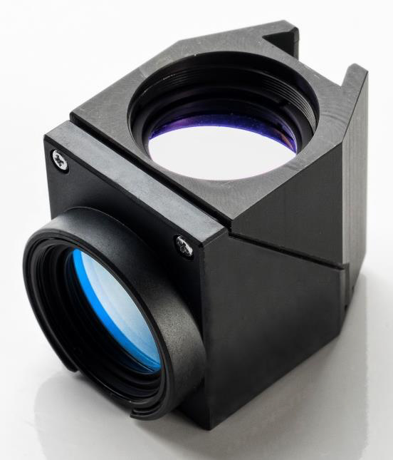
Figure 1. Fluorescence filter cube containing hard-coated, next-generation thin-film optical filters.
Most excitation and emission filters are bandpass filters. This means that they transmit light at a specific wavelength, or range of wavelengths, while blocking the adjacent spectrum on either side. Beamsplitters, on the other hand, are dichroic or polychroic filters that are set at an angle. They work by transmitting certain wavelengths while reflecting others.
1.2 Next-Generation Thin-Film Optical Filters
There are many options when choosing fluorescence filters, but the gold standard are hard-coated, thin-film optical filters. They are made by depositing alternating thin layers of materials with special optical properties onto a substrate such as borofloat or fused silica. These next-generation thin-film optical filters remove unwanted light that can result in sensor overexposure and masked target signals. This allows for accurate identification and measurement of fluorescently tagged biomolecules, which is important for the growing field of quantitative fluorescence microscopy. At the same time, next-generation filters increase signal sensitivity, which allows for detection of infinitesimally small fluorescent light emissions from biological samples. Achieving this level of detection is essential for optimizing the performance of instruments such as flow cytometers, DNA sequencers, and Raman spectrophotometers.
2. Excitation and Emission Filter Considerations
2.1 Bandpass Design
Bandpass filters are essential components of fluorescence systems because they can be optimally targeted to the excitation and emission spectra of each fluorophore, or set of fluorophores (See Figure 2). There are two fundamentally different approaches to designing a bandpass filter. The first relies on stacked Fabry-Perot resonant cavities, while the second combines individual longwave-pass (LWP) and shortwave-pass (SWP) filters to form both edges of the bandpass. Cavity filters are inherently symmetric in shape while LWP and SWP designs can be made asymmetric, which can help to lower cost in certain situations.
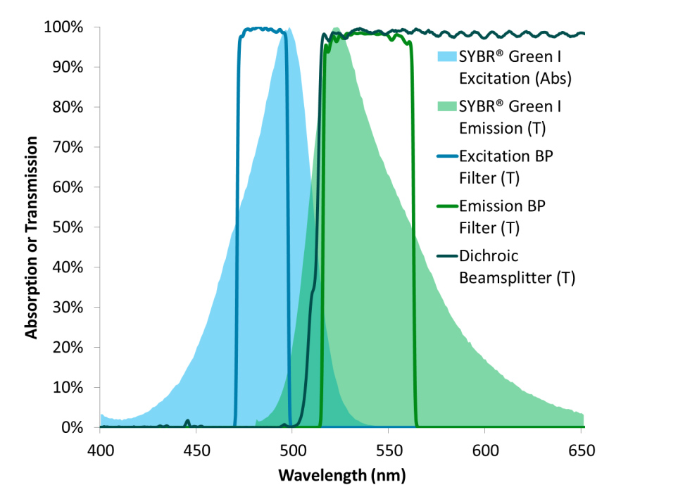
Figure 2. Excitation and emission spectra of SYBR® Green I DNA binding stain overlaid with the transmission spectra of a set of optical filters designed to optimize detection and visualization of this fluorophore.
Both types of bandpass filters are paired with blocking elements in order to block transmission of light outside the passband, or region of high transmission. Out-of-band blocking is generally described by the optical density (OD) of the filter, defined as the negative log (base 10) of the transmittance (T). Blocking elements can be dielectric blockers such as additional SWP and LWP filters, or non-dielectric elements such as light-absorbing colored glass. However, the latter introduce cost, autofluorescence, and reliability concerns.
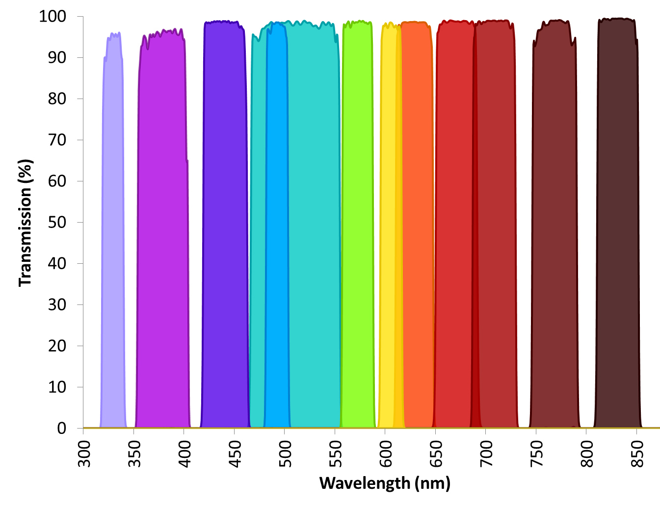
Figure 3. Typical transmission levels of several different excitation and emission bandpass filters. High transmission is able to be achieved across the electromagnetic spectrum from UV to IR wavelengths. All filters are blocked to a level of OD6 or greater.
Figure 3 shows typical transmission response, or %T, as a function of the electromagnetic spectrum, for a variety of common excitation and emission filter wavelengths and bandwidths. These filters are fully blocked, meaning all wavelengths outside the passband are rejected, to OD6 or greater, to ensure optimized S/N ratios.
Although soft coating alternatives exist, hard-coated thin-film bandpass filters are more durable and offer higher in-band transmission, as well as steeper transitions to high out-of-band (OD) blocking. All of these factors allow for enhanced S/N in fluorescence systems. This can greatly improve outcomes for applications such as laser scanning fluorescence confocal microscopy, where S/N dictates the achievable contrast of the final image.
2.2 Slope and Squareness
The “squareness” of a signal is also important because it enables a steeper transition between high %T in the passband to high OD blocking. The squarer the filter shape, the more vertical the edges of the bandpass (or edge) filter. This might be critical in Raman spectroscopy, for example, where the laser line filter needs to have a steep cut-off edge to modulate the laser source. Conversely, the laser blocking filter, often a Raman longpass, needs to have a steep cut-on edge to completely block the light from the laser. Designing bandpass filters with steeper slopes, or improved squareness, is a relatively simple matter of adding more cavities to the filter (see Figure 4). Improving the slope of the LWP / SWP designs is much the same, although in this case more layers are added.
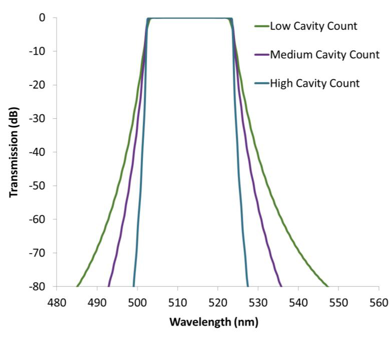
Figure 4. Filter “squareness” is a direct function of the number of resonant Fabry-Perot cavities in cavity filters, or the number of layers in LWP / SWP designs.
However, adding cavities can introduce undesirable ripple and loss to the passband, which translates into decreased contrast in the final image. Fortunately, a novel optical thickness monitoring approach allows for increased cavity counts while maintaining low passband ripple. This system works by continually measuring filter function and compensating for thickness errors associated with prior layers. Figure 5 demonstrates how high transmission and low ripple were able to be repeated using this technique for four coating runs of the same high cavity bandpass filter design from Figure 4. This monitoring approach allows filters to meet high-performance system requirements, without compromising precision or accuracy.
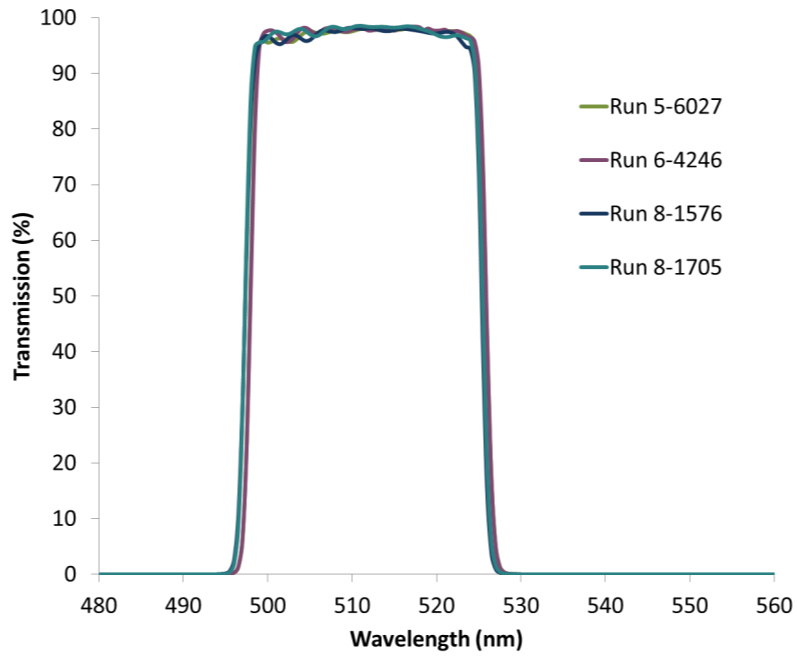
Figure 5. Repeatability of high cavity count filters. Shown above are four runs of fully blocked high cavity count bandpass filters from three different chambers.
2.3 Out-of-Band Blocking
Fluorescence detection filters are characterized in terms of blocking level, particularly with respect to the overlap of the excitation filter. Out-of-band blocking levels of 5 to 6 OD are recommended for most fluorescence applications. However, special consideration should be given to crossover points, or wavelength ranges where excitation response declines and emission response inclines. In most cases, blocking coverage should be greater at these points since insufficient blocking in this region could result in undesirable light leakage. For example, if the emission filter does not adequately block the much brighter excitation light, it will overwhelm the weaker emitted fluorescence light from the specimen, resulting in poor S/N.
Figure 6 shows blocking levels of the bandpass filter depicted in Figure 5. This filter has all the bandpass and blocking layers on a single side of the substrate, which improves transmission and reduces cost. An anti-reflection (AR) coating on the back of the substrate improves transmission at nominal extra cost.
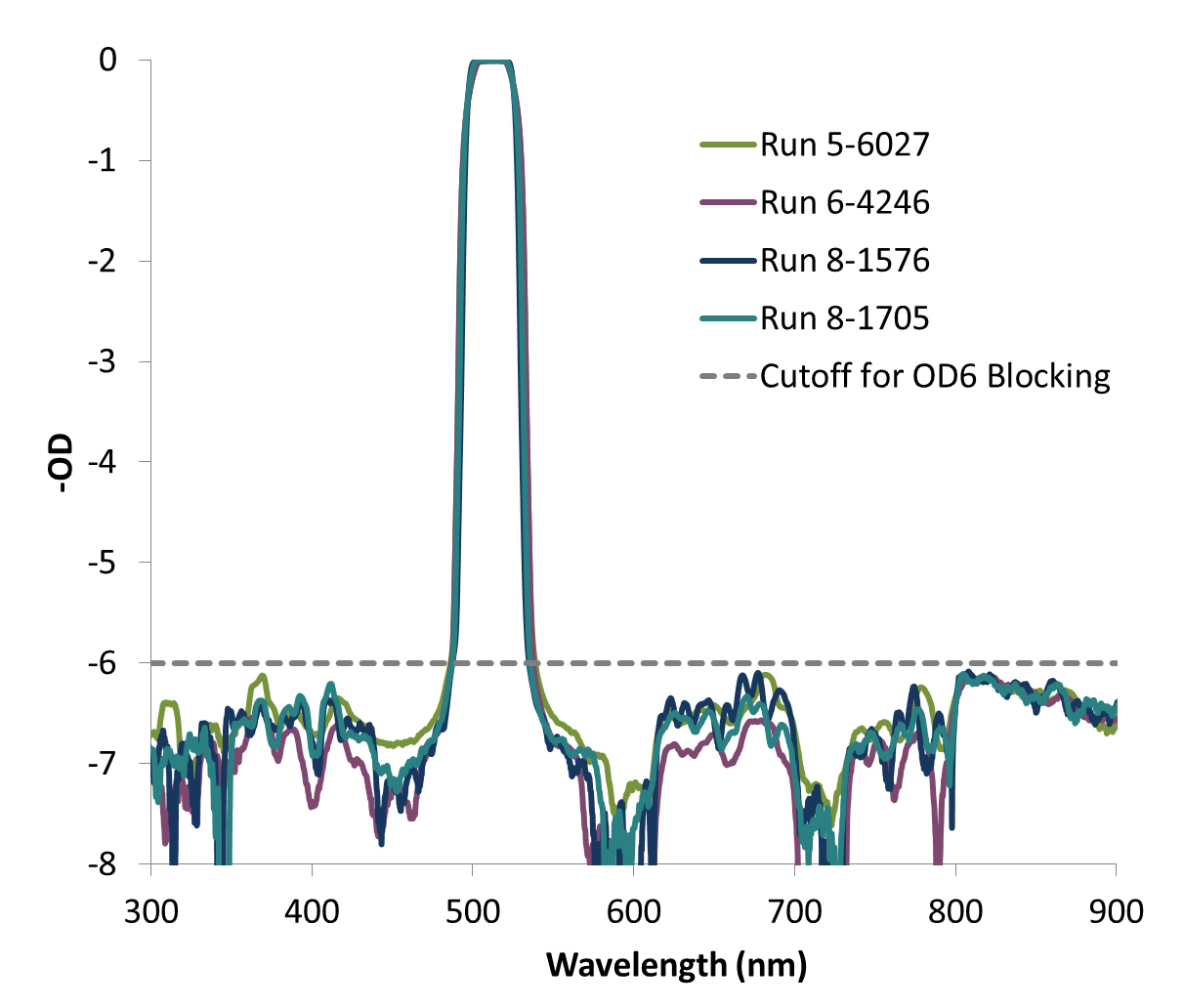
Figure 6. Repeatability of blocking levels for the four runs of the high cavity count bandpass filter seen in Figure 5. All are blocked to a level of OD6.
2.4 Multi-Bandpass Filters
The latest bioimaging systems require the flexibility of multiple bands of illumination for both excitation and emission. Next generation thin film hard coatings address such demanding applications by delivering high transmission and low ripple for multiple passbands (see Figure 7). Multiband filters are typically specified in terms of transmission bands and blocking (rejection) bands.
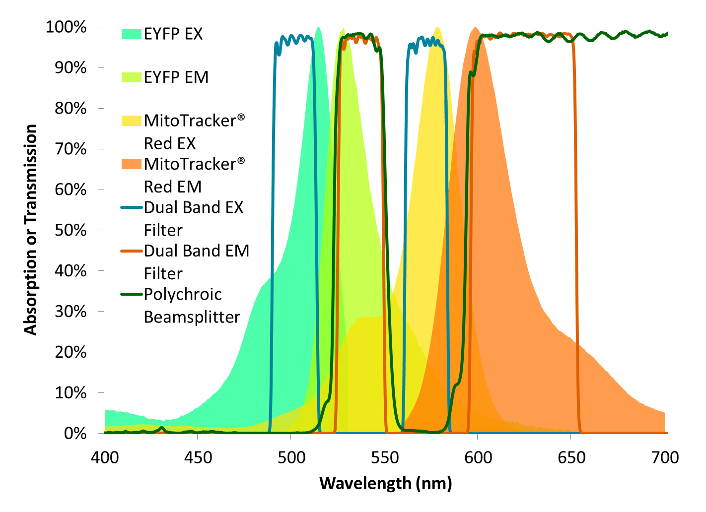
Figure 7. Excitation and emission spectra for both EYFP and MitoTracker® Red overlaid with the transmission spectra of a dual-band filter set designed for these fluorophores.
Transmission levels averaging 90–95% are typical within the passband, while average blocking levels range from 5OD to 6OD between bands. Typically, in multiband filters, the gaps between the passband and blocking bands are 2–3% of wavelength, although narrower spectral gaps can increase cost. In general, cost can be reduced by avoiding specifications such as steep transition slopes and > 6OD blocking levels, unless these are required by the system.
3. Beamsplitter Considerations
3.1 Dichroic and Polychroic Filters
The function of a dichroic filter is to separate the spectral bands of both the excitation and emission light with minimal signal loss and minimal spectral gap between bands (see Figure 8). Sharp transitions from reflection to transmission enhance image contrast for many applications, including fluorescence and multispectral imaging. For implementation in these systems, dichroic filters must possess low angle shift, low polarization splitting, and excellent flatness of both reflected and transmitted wavefront to eliminate any noticeable focal shift, which could be detrimental to any imaging system. This is especially critical for applications such as total internal reflection fluorescence (TIRF) and structured illumination microscopy.
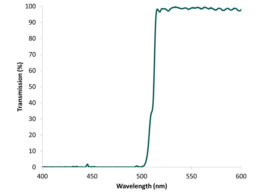
Figure 8. Transmission of a dichroic beamsplitter measured at a 45 degree angle.
Multiband systems push the performance envelope even further, and require a comb-like performance that separates multiple excitation bands from multiple emission bands. These types of filters provide the ability to study cells in real time. This is especially critical in the field of cancer research for real-time analysis of stem cell growth. Figure 9 shows the spectra for a polychroic (multiple wavelength) beamsplitter.
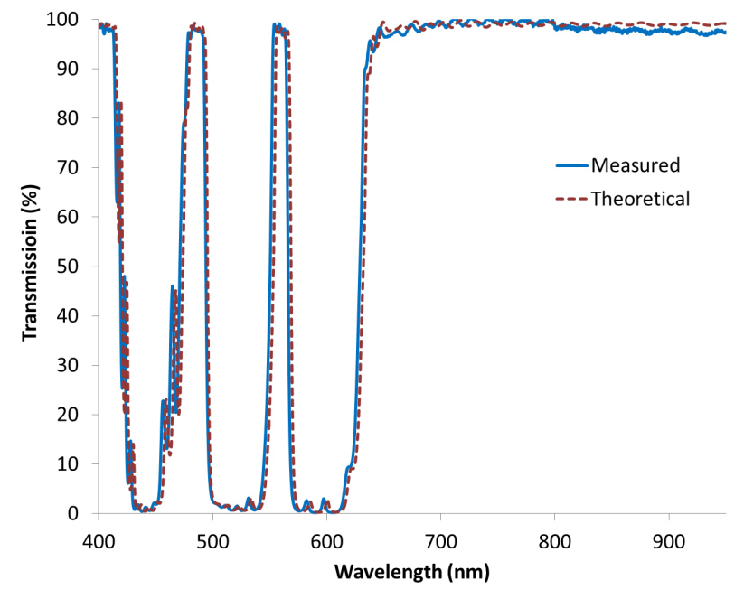
Figure 9. Comparison of measured vs. theoretical spectra for a quad-band polychroic beamsplitter. Transmission levels were measured at a 45 degree angle.
4. General Filter Considerations
4.1 Coating Stress
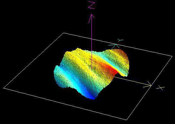
Deposition of a coating normally produces stress within the thin film which can often result in a change in the flatness of the optical substrate. The type of stress, tensile or compressive, depends on the type of coating process used as well as details of the coating conditions. Typically, this stress results in a slight curvature of the substrate, creating a hill or bowl shape. This curvature can be measured using an optical interferometer as shown in Figures 10 & 11.
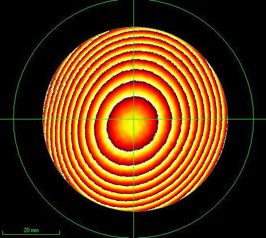
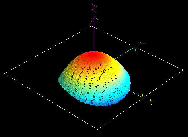
Figures 10 & 11. Curvature of substrate due to coating stress. The figure on the left shows the measured phase obtained using an interferometer while on the right is the measured optical path difference as compared to a reference flat.
The effect of this curvature on an optical beam or image is to some degree like that of a lens, and thus may introduce unwanted distortion into the optical system. This may become important, for example, when the accurate positon of an array of wells containing fluorescently tagged DNA needs to be measured from an image produced by a CCD detector. Accurate measurements can only be made if the effects of curvature are minimized.
A number of techniques can be used to offset stress-induced curvature. Fortunately, the simplest fix may simply be to increase the thickness of the substrate since the use of additional techniques would increase filter cost. Therefore, maintaining a repeatable stress, preferably low in level, is crucial for keeping both yields high and costs low.
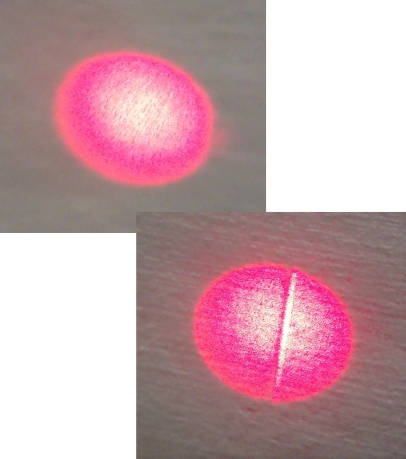
Any variation in thickness, parallelism, or index of refraction across the filter will also result in distortion, but only for transmitted light. This type of distortion, called transmitted wavefront error (TWE), can also be determined using an interferometer (see Figures 12 & 13). Advances in instrumentation design have driven the levels of TWE performance such that measureable amounts of TWE related to the coating need to be carefully managed in order to optimize image quality.
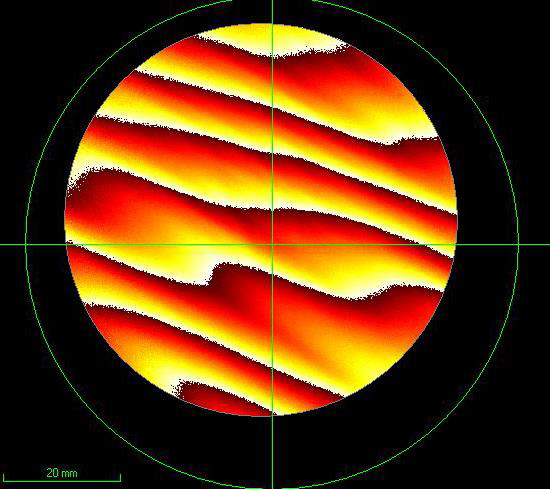
Figures 12 & 13. TWE, or change in optical path length in transmission. The figure on the left shows the measured phase using an interferometer while the right shows the variation in optical path length through the part.
4.2 Cost and Selection
Many factors directly affect the cost of a filter, particularly when large quantities are produced. While selection of many of these product attributes is common and straightforward, sometimes unanticipated costs and corresponding price impacts are incurred with specifications that haven’t weighed the value of the attribute with the cost sensitivity. The table below indicates relative sensitivity of some common filter attributes and their impact on pricing.
Table 1
Optical Filter Attributes and Relative Cost Sensitivity
| Filter Attribute | Price Impact | ||
|---|---|---|---|
| Low | Med | High | |
| Size (Area) | X | ||
| Flatness | X | X | |
| Transmitted Wavefront | X | ||
| Wavelength / FWHM Tolerance | X | ||
| Spectral Steepness | X | ||
| Absolute vs. Average Blocking | X | ||
| Width of Total Blocking Range | X | ||
| Substrate Material | X | ||
| Custom Sizing | X | ||
| Center Wavelength | X | ||
| FWHM | X | ||
| SWP or LWP | X | ||
Summary
The optical filters integrated into fluorescence imaging and detection systems are arguably the most important elements that define system performance. Next-generation thin-film optical filters offer improvements in transmission, blocking, and both transmitted and reflected wavefront properties. This translates into bright, high-contrast images and accurate detection of target molecules. Alluxa offers these high-performance filters at any production volume and at competitive price points. For any fluorescence based instrument, our team of experts will help you create custom filters to optimize system performance.
Why Alluxa?
Alluxa’s team of experts has delivered key innovations to the field of optical thin-films. In addition to designing and constructing all of our own custom optical thin-film coating equipment, we invented a novel plasma deposition coating process that both increases the performance of our optical filters and decreases the time it takes to produce them.
By combining these innovations with state-of-the-art automation, proprietary control algorithms, and precision monitoring during the coating process, we are able to deliver low-cost, high-performance, custom thin-film optical filters for any application.
Contact Alluxa for more information at info@alluxa.com
or visit our website at https://alluxa.com
All content copyright ©2020 Alluxa, Inc.
