Cone Half Angle (CHA)
CHA and F-Number
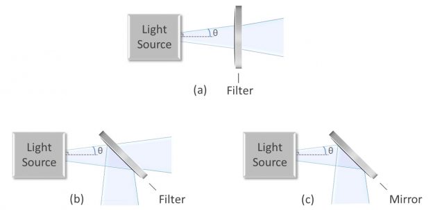
Cone half angle (CHA) describes the extent to which an incident beam is converging or diverging. It is defined as the angle between the AOI of the incident beam and the most oblique marginal ray (Figures 1a-1c). Therefore, a 0˚ CHA is synonymous with collimated light, and larger cone half angles designate a pronounced convergent or divergent beam.
Figures 1a-1c: Diagrams showing uncollimated light and cone half angle for (a) an optical filter at 0° AOI (b) a dichroic filter at 45° AOI, and (c) a high-reflectivity mirror at 45° AOI.
Both numerical aperture (\(NA\)) and f-number (\(F\#\)) are alternate properties used to describe the cone of a beam. The following formulas derived using Abbe’s Sine Condition relate CHA and f-number:
$$ {\theta = arcsin\left(\frac{1}{2nF\#}\right)} $$
$$ {F\# = \frac{1}{2n sin(θ)}} $$
Where:
- \(θ\) = half cone angle
- \(n\) = refractive index of incident medium ( \(n_{air} ≈ 1\) )
- \(F\#\) = f-number
Numerical aperture is defined as the product of the incident medium refractive index and the sin of the CHA. A variation of Snell’s law shows that \(NA\) will remain constant as light passes through different media:
$$ { NA = n_1 sin(θ_1) = n_2 sin(θ_2)} $$
Effect of CHA on Optical Filter Spectra
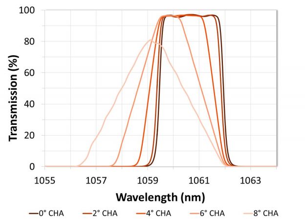
Like increasing AOI, increasing CHA values result in a blue shift of interference filter spectra. However, because cone angle essentially represents an average of many angles of incidence, the spectral shift due to CHA is less dramatic than the shift due to tilt. The averaging effect also results in filter edges that become less steep as CHA increases. Bandpass filters, for example, will exhibit a cone shaped passband with a large CHA instead of the square spectral shape seen with collimated light. The effect of CHA is especially apparent for narrowband and ultra-narrow bandpass filters, which show decreased transmission even when CHA is relatively small (Figure 2).
Figure 2: Graph demonstrating the effect of differing cone half angle values on optical filter transmission spectra. Theory data for a narrowband filter is shown at 0° AOI with average polarization.
Although it is common to see cone angle reported as an AOI range instead of in terms of CHA or f-number, the effects of AOI and CHA differ, so they should be stated as separate parameters. Doing so will allow the designer to optimize the optical filter appropriately.
Evaluating CHA
Directly measuring optical filters at the specified cone angle is difficult in many cases because commercial spectrophotometers and custom spectral analysis systems do not have a variable CHA setting. Most commercial spectrophotometers have an inherent CHA of between ~2° and 4° that can be reduced by a fixed amount when apertures are introduced into the beam path. Other instruments, such as tunable lasers and Alluxa’s custom-built HELIX System, have a collimated beam.
Because direct measurement is difficult, spectral performance at a relatively small specified cone angle can be calculated analytically by using offsets for each spectral feature. Similar to AOI, these offsets are determined from the theory traces. Likewise, filters used in systems with a large CHA can be evaluated using an optimization algorithm where the optimized output is modeled at the specified CHA.
Why Alluxa?
Alluxa’s team of experts has delivered key innovations to the field of optical thin-films. In addition to designing and constructing all of our own custom optical thin-film coating equipment, we invented a novel plasma deposition coating process that both increases the performance of our optical filters and decreases the time it takes to produce them.
By combining these innovations with state-of-the-art automation, proprietary control algorithms, and precision monitoring during the coating process, we are able to deliver low-cost, high-performance, custom thin-film optical filters for any application.


