Distortion in High Performance Reflectors
Alluxa Engineering Team
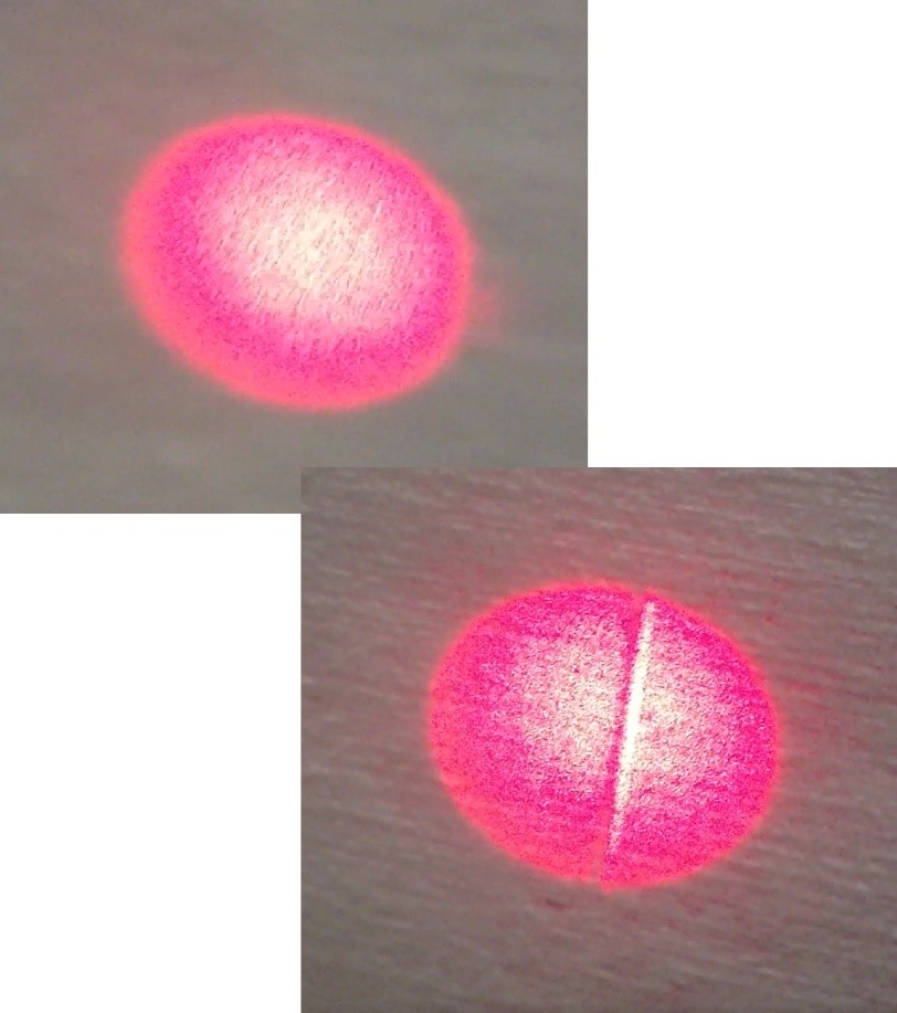
Figure 1. Laser beam profiles comparing the beam shape before and after reflection from a high-performance mirror, as photographed on a display screen.
Introduction
High-performance optical reflectors often serve as critical components in numerous applications. From high-power laser systems to quantum metrology, thin-film mirrors are nearly indispensable. While these components typically deliver excellent performance, certain applications require careful consideration of potential distortion effects that can impact system-level performance. This paper focuses on phase effects and how they can result in undesired distortion in the reflected optical beam – such as shown in Figure 1. The motivation is both to increase general awareness and help system designers manage such effects.
High Performance Mirrors
Modern high-performance mirrors are available in two primary categories: metallic and dielectric. Although both offer good reflectivity, each has distinct advantages for specific applications.
Metallic mirrors, constructed from materials such as aluminum, silver, or gold, provide reflectivity over a broad spectral range with typical reflectivity values ranging from 90-98% in the visible spectrum. Constructed using a single metal layer with a protective overcoat to reduce tarnishing and increase robustness, their simplicity makes them a cost-effective choice. When higher performance or a specific wavelength dependent performance modulation is needed, more complex solutions are required. Metallic mirrors also have limitations such as susceptibility to aging and oxidation, inherent absorption losses, lower LIDT and poor performance for some UV wavelength ranges when using protective overcoats.
Dielectric mirrors, in contrast, are constructed from a large number (50<N<1000) alternating layers of high and low refractive index materials, typically oxides. These complex mirrors are capable of exceptionally high reflectivity, with values exceeding 99.999%, such as the mirrors used in the LIGO gravitational observatory. The great flexibility of their construction enables them to be tailored for specific performance requirements for wavelength bands throughout the UV, visible and IR wavelength regions. Further versatility is derived from the minimal material absorption characteristics of oxides. Low absorption is typically equated with superior damage thresholds, making dielectric mirrors particularly valuable for high-power laser applications.
Phase Effects and Distortion
Both metal and dielectric mirrors affect the phase of the light passing through its constituent layers. Metal mirrors, however, experience phase shifts upon reflection that depend mainly on the complex refractive index of the metal. Their phase behavior is generally simpler since reflection occurs primarily at the metal surface. Metal coatings typically impart near-constant, large phase shifts close to 180° for reflections in the visible or near-infrared as shown in Figure 2.
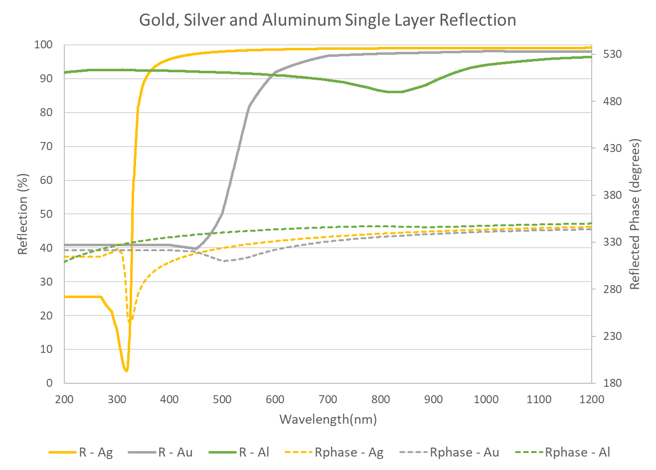
Figure 2. Reflectance and phase shifts for bare gold, silver, and aluminum mirrors at normal incidence.
One of the simplest examples of a dielectric reflector is a single stack of layers with alternating high and low index of refraction. The optical thickness of the layers is one quarter of the center wavelength of the reflection region, called a quarter-wave (QW). As shown in Figure 3, the QW stack delivers high reflection and a relatively smooth phase profile, with minimal phase effects across the reflection band. The bandwidth of the mirror, the effective high reflectivity region, is a function of the difference in index of refraction of the two materials.
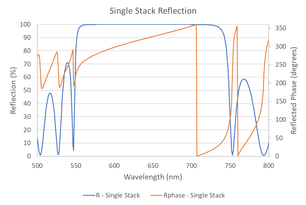
Figure 3. Reflectance and phase shift for a single stack of TiO2/SiO2 dielectric quarterwaves at normal incidence.
Temporal Distortion
An example of temporal distortion that is easily visualized is the reflection from a linearly chirped Bragg mirror. The mirror consists of a series of QW stacks, each centered at a different wavelength, combining to create a broad band reflector. As can be seen in Figure 4, different wavelengths are reflected at different depths within the dielectric stacks. The result of this depth/travel difference is a difference in the optical delay time seen by each exiting wavelength. This group delay due to depth of penetration is added to the phase effects that occur at the boundaries between the individual stacks which make up the broad band mirror.
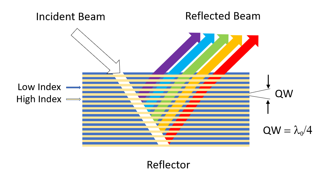
Figure 4. Reflection from a Bragg mirror quarter wave stack.
The time delay is called group delay (GD) and is defined as the change of phase with respect to frequency. In the example of a QW stack, the areas of rapid change in phase with wavelength are clearly visible, particularly at the edge of the QW stack. In this region the GD is large and becomes most pronounced in broadband mirrors constructed from multiple quarter-wave stacks, where phase transitions between stacks create commensurate group delay variations. Group delay, and the change in group delay with frequency, known as group delay dispersion (GDD) or chromatic dispersion, are the primary temporal distortion concerns in dielectric mirrors. The group delay for the single stack of Figure 3, calculated directly from the phase, is shown in Figure 5.
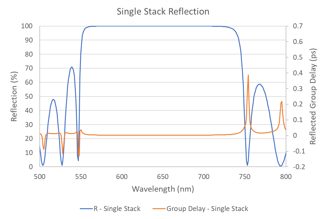
Figure 5. Reflectance and group delay for a single stack of TiO2/SiO2 dielectric quarterwaves at normal incidence.
The magnitude of GD and its phase derivative, GDD, depends on several factors: the number of dielectric layers, refractive index contrast, design wavelength, bandwidth, and angle of incidence. As the number of layers increases, the effect intensifies not only due to increased physical thickness but also because of the complex interference created by the many reflections and their associated phase shifts.
GDD is particularly significant in the fields of ultrafast laser systems and optical communications. In ultrashort pulses GDD can cause pulse broadening, introduce frequency chirp, and create higher-order dispersion effects. As with GD, the impact of GDD is most notable in broadband mirrors made from multiple quarter-wave stacks. Phase transitions between stacks can create substantial delay variations and limit the bandwidth of regions of good phase or low distortion.
In optical communications, varying group delays between frequency components can result in both temporal broadening or compression of propagating pulses. The measurable effect is a distortion of the transmitted signal. This sort of temporal distortion causes pulse broadening, frequency chirp, and higher-order dispersion effects in ultrashort pulses. Solid understanding of GD and GDD are often of critical importance in the design of optical elements for ultrafast laser systems.
Spatial Distortion
While GD and GDD are well known effects in the time domain, a less commonly considered optical distortion is derived from changes in phase with incident angle. Called the Goos-Hänchen shift when referring to reflection from a single layer, it is a lateral displacement of the reflected beam relative to its expected geometric reflection point. In this event, the incident light, consisting of an electromagnetic field, doesn’t reflect exactly at the boundary of the substrate. Instead, it extends into the substrate as an evanescent field as shown in Figure 6. The result is a shift in the reflected output.
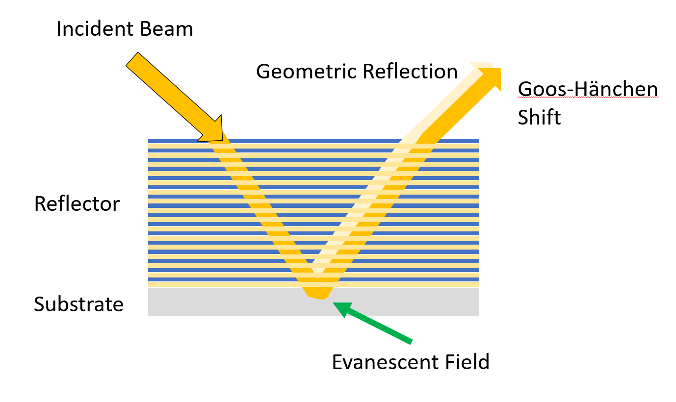
Figure 6. Goos-Hänchen shift on reflection due to evanescent field.
For a perfectly collimated beam of light of a single polarization, the entire beam sees the same, very small lateral shift. The shift is typically so small, on the order of microns, the effect is rarely noticeable or even measurable. In the previously considered QW reflector stack (shown in Figures 4 and 5), a lateral shift of roughly 10 micrometers arises for wavelengths near 725nm. This effect is depicted in graphical form in Figure 7.
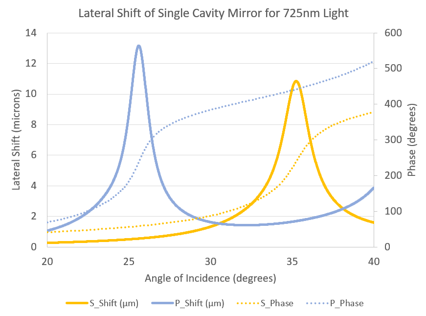
Figure 7. Lateral shift for single stack TiO2/SiO2 mirror.
While these phase effects are always present in optical systems, in most applications an overall lateral shift on this order is not significant and is easily compensated for. However, for a case where the mirror is designed to highly reflect the visible wavelength region while also maintaining some desired phase response the effect can be more pronounced. In a multi-beam laser system, when phase characteristics are to be preserved between and within each of the individual laser wavelength bands, the complexity of the mirror results in the possibility of much larger beam distortion increases.
For example, a fluorescent microscopy system might combine multiple laser wavelengths into a single beam as shown in Figure 8. As the angle of incidence (AOI) of each laser on the main high reflector is varied, each individual wavelength might see beam distortion effects due to phase changes with angle.
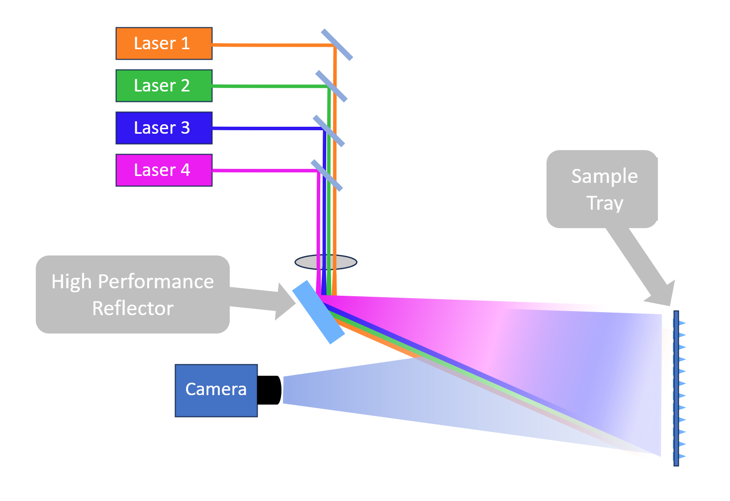
Figure 8. Multi-wavelength fluorescence application with high performance main reflector.
For this sort of imaging application, distortion of the laser beam can be problematic. For a theoretical, perfectly collimated beam of light, the entire beam would see the same lateral shift. However, most incident laser beams are somewhat divergent or convergent. Bundles of rays covering a range of incident angles are inherent to laser optical system design. Since the phase change and lateral shift magnitude varies with the angle of incidence, each discrete incident ray experiences slightly different phase and lateral shifts. This can lead to a shift in beam position and shape distortion of the reflected beam.
For a normal gaussian laser beam, the variation in propagation angle across the beam, and thus AOI on the reflector, will have a distribution as illustrated in Figure 9. The optical layout geometry determines what portion of the incident beam is incident on the mirror at a given AOI, and thus what lateral shift will occur within each section of the beam.
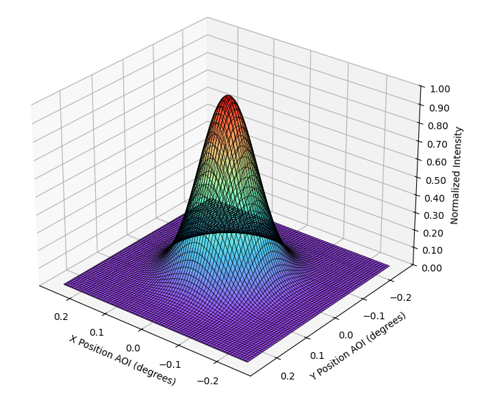
Figure 9. Distribution of intensity vs AOI for a gaussian laser.
For a given AOI the light will shift laterally, leaving behind a dark area in the beam profile, resulting in a distorted beam. Assuming the variation in incident angle is given by the beam distribution shown in Figure 9, and the optical layout is as shown in Figure 10, this appears as a vertical dark line.
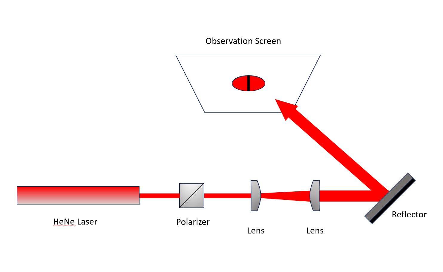
Figure 10. Optical Layout for Lateral Shift Measurements.
The dark area is where the lateral shift is at its maximum, while the shifted light reappears as a bright line shifted to the right as shown in Figure 11. The vertical line results from the fact that the incident angle is dominated by the geometry of the layout. For the examined layout, the reflected angle is around 36 degrees, while the variation of angle within the beam itself is much smaller, only about +/- 0.25 degrees. The effect of the larger angle dominates and, given the layout geometry, any vertical line on the mirror is roughly at the same AOI.
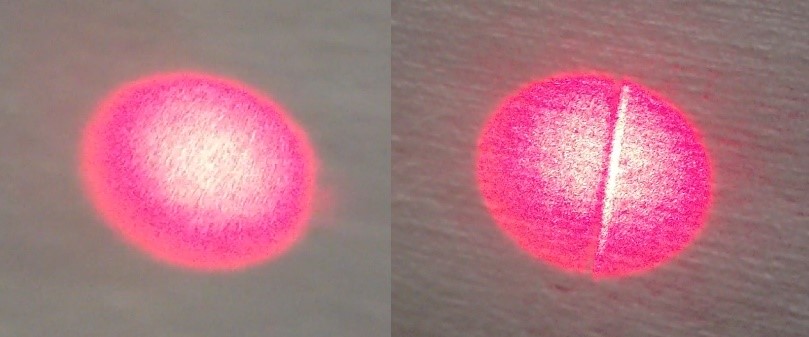
Figure 11. Example of normal beam spot and beam showing lateral shift.
The lateral shift of this reflector is on the order of one millimeter, which is unusually large. In this case the customer requested a high reflection mirror over the entire visible wavelength range but also required the phase be maintained at a constant fixed value within selected wavelength sub-bands. This required the designer to shift the naturally occurring phase changes away from the selected sub-bands. This preferential phase-change redistribution produced a stack-up of highly variable phase in the broader spectral region outside the sub-bands, thus creating large lateral shifts in the region outside the selected wavelength bands. These lateral shifts could be moved around in wavelength however, since dielectric filter characteristics shift to shorter wavelengths for larger AOI. This increases the likelihood of system performance issues.
The optical system layout and the imaged lateral shift discussed above are a particularly clean demonstration. However, distortions from lateral shifts can be much more complicated. Figure 12 shows a more detailed photograph of this lateral shift effect. Here the reflector is illuminated using a gaussian HeNe laser beam with divergence as previously described.
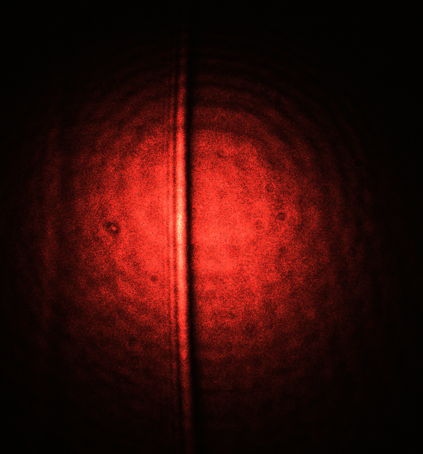
Figure 12. Black bar filter measurement example.
The Goos-Hänchen shift and lateral shifts in general are highly polarization dependent. Different polarizations experience different phase shifts leading to varying beam shape distortion. In this scenario the beam is unpolarized or partially polarized, containing both s and p-polarized light.
For the un-polarized HeNe laser beam, the magnitude of the lateral shifts for s and p-polarized light at different angles at 633nm are shown in Figures 13a and 13b.
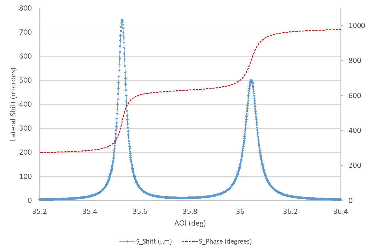
Figure 13a. Phase and Lateral Shifts vs. AOI for S-pol light for the complex design.
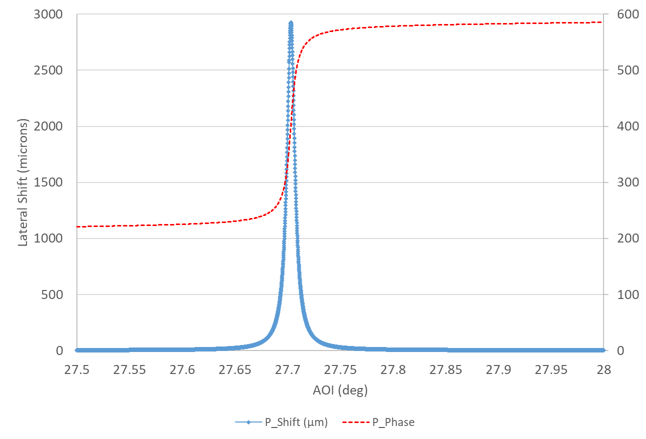
Figure 13b. Phase and Lateral Shifts vs. AOI for S-pol light for the complex design.
Large phase shifts with angle and large phase changes with frequency often occur in tandem. Both depend on optical thickness/number of layers of the films used in constructing the mirror. If the group delay is known to be large at some wavelengths in a particular mirror design, this increases the likelihood lateral shifts of a large magnitude may develop. For the mirror design of Figure 12, the group delay values at the HeNe wavelength (633nm) used to measure the lateral shift, are shown in Figure 14. The GD is seen to be large and very similar in shape to the calculated lateral shift values. The GD however, is derived from frequency dependent rather than angle dependent phase changes.
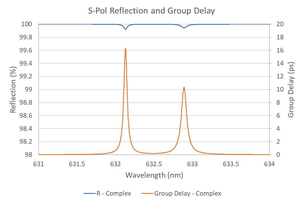
Figure 14. Detail of s-polarization reflectance and group delay for complex design.
When the user or filter designer suspects phase effects may be a factor in an application, it is best to thoroughly evaluate the frequency and angular response of the optical filter. Group delay and/or lateral shift information should be carefully surveyed at the design phase before the filter is manufactured. However, this information is not readily available for many off standard or off-the-shelf catalog filters. It is often possible to obtain basic or typical phase information for a given class of designs by contacting the manufacturer.
Conclusion
Phase effects in high performance reflectors can introduce both temporal and spatial distortions in optical systems. These effects may have variable significance at the system level performance, but it is important that the system designer or user be knowledgeable of their likelihood in a particular application. In the case of complex multilayer dielectric mirrors, this level of foresight can be critical and less costly.
In determining whether phase effects may be an important factor in a given application, it is of course best to contact the manufacturer directly. In the case of specialized designs, the manufacturer’s thin film designers can provide the precise information needed for the specific application. Even for many standard products where phase information is not available by default, experienced customer engineers can offer useful guidance and provide information to help the user determine if a given application might be sensitive to these effects as well as assist in mitigating these effects, if necessary.
The inherent high performance capabilities of dielectric reflectors ensure their ubiquity across a wide range of diverse industrial sectors. Therefore, challenges such as lateral shift distortions must be predicted, considered, and adapted to wherever precise and efficient light control is of utmost importance. For further information please contact the team at Alluxa Inc for all your optical filter applications from life sciences to aerospace.
References:
[1] “Lateral Beam Shifts and Depolarization Upon Oblique Reflection from Dielectric Mirrors” – Annalen der Physik – 2024 – Xiao et al.
[2] “Lateral shifts and angular deviations of Gaussian optical beams reflected by and transmitted through dielectric blocks: A tutorial review” arXiv:1912.08632v1 [physics.optics] 18 Dec 2019.